In my previous bog HERE, I walk through the steps of creating a backup directory on a QNAP NAS, enable SFTP connections, and created a service account. In this blog, I will complete the backup configuration in the SDDC manager for this VCF 9 deployment in my home lab.
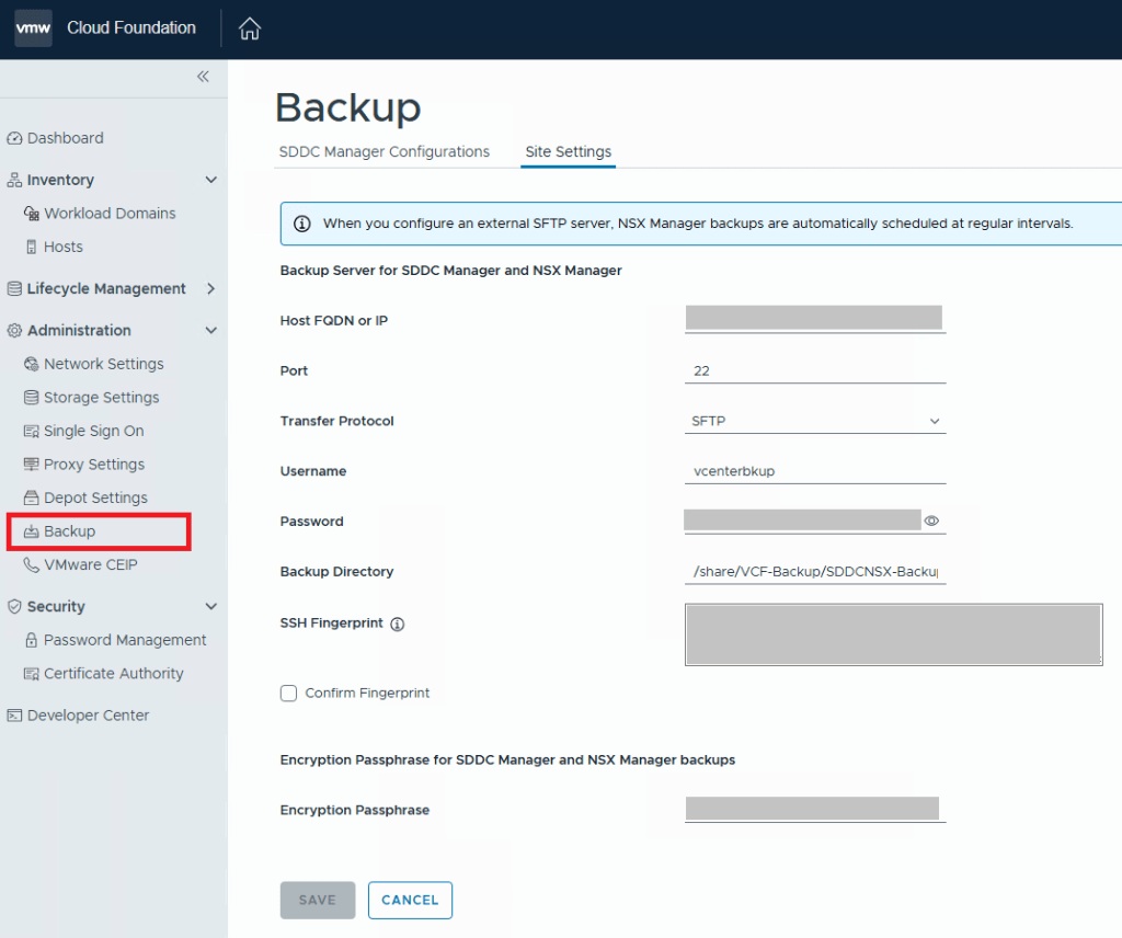
For VCF 9.0.X, and previous versions, you log into the SDDC manager, and click on Backup on the left side menu under Administration. On the “Site Settings” tab, you then fill in your specifics for backup configuration.
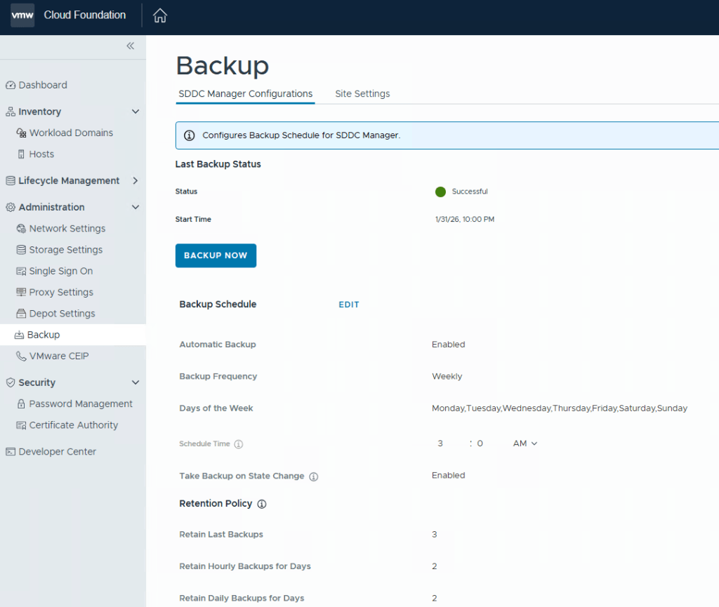
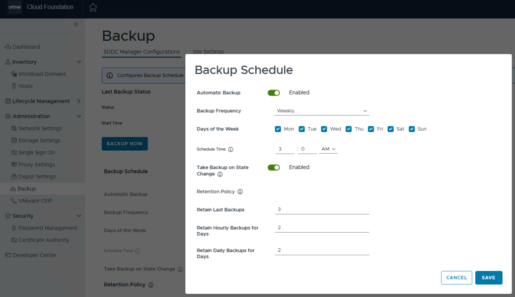
After you click the Save button, go back to the “SDDC Manager Configurations” tab, and now you will be able to click “EDIT” next to the backup schedule.
You can define the backup schedule to suit your needs depending on how busy your environment is, and how often workload domains are updated. This schedule however, does not reflect your NSX backup which is counter intuitive considering enabling the backups in the SDDC manager also enables the backups in NSX. Just not the schedule.
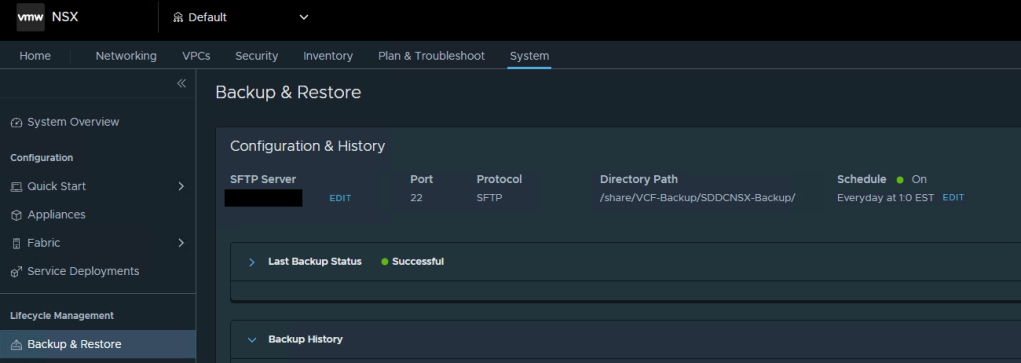
To modify the NSX backup schedule, you’ll need to log into NSX, click the “System” tab, and then select “Backup & Restore” under Lifecycle management on the left menu.
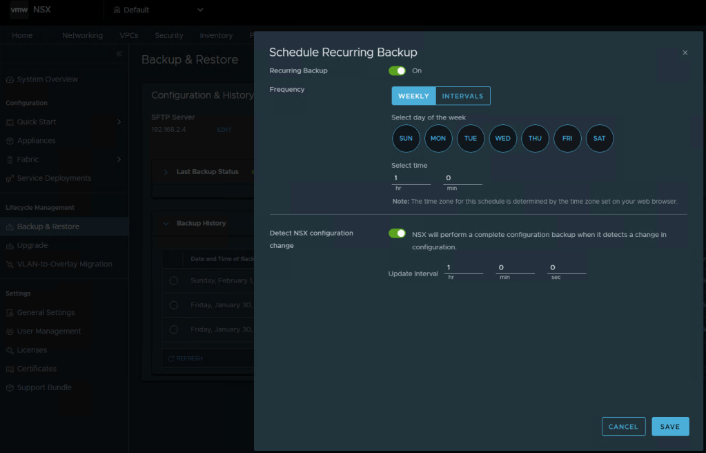
Here you can click “EDIT” to adjust the NSX backup schedule to suite your needs. Click SAVE when finished.
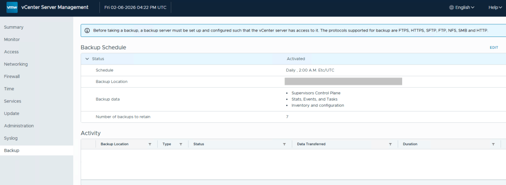
Lastly, we still need to define the backups schedule in the vCenter 5480/vami administration page.
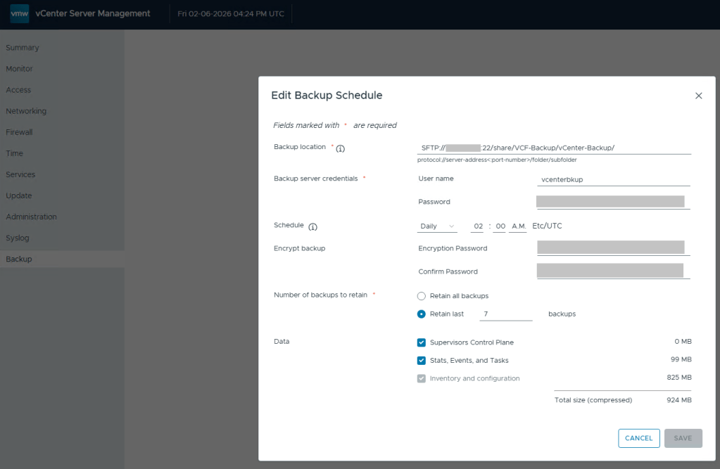
Define the backup schedule that will suit the needs for your environment. Keep in mind that when you install updates/upgrades to the VCF environment, the pre-check will fail if there’s not a recent backup within the last 24 hours. My advise here would be to schedule daily backups to avoid the precheck critical failure. Honestly, it should just be a warning, but I digress…
After you define a backup schedule, it’s a good idea to manually kick off a backup job to be sure the configuration works.
Continuing my series on my new VCF 9 Home Lab build (My VMware Cloud Foundation 9 Home Lab), in this post I’ll go over the basic setup for SFTP backups that need to be configured for the SDDC, NSXT, and vCenter, using my QNAP NAS.
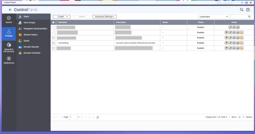
First, a service account should be created for these backup jobs. In this example, I have a service account called ‘vcenterbkup’ already created for my old VMware lab, and just plan to reuse it. You can either make this user part of the administrators group to allow SSH/SFTP connections, or you can tinker and edit the SSH configuration files (e.g., /etc/config/ssh/sshd_config) by adding AllowUsers directives.
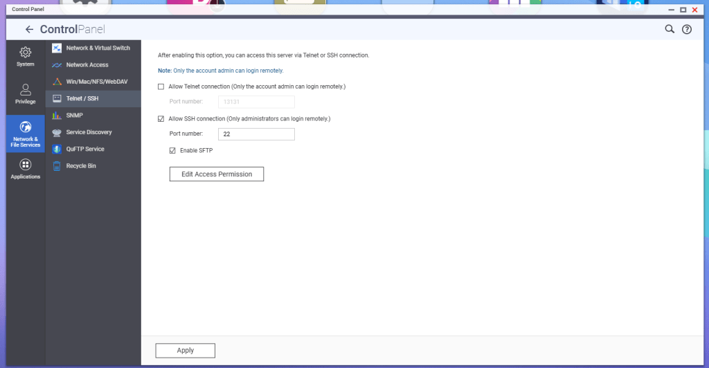
According to QNAP, in order to enable SFTP connections to the NAS, the SSH service must be enabled first, and then the SFTP enablement will be available. Go to Telnet/SSH in the Control Panel, and enable these services.
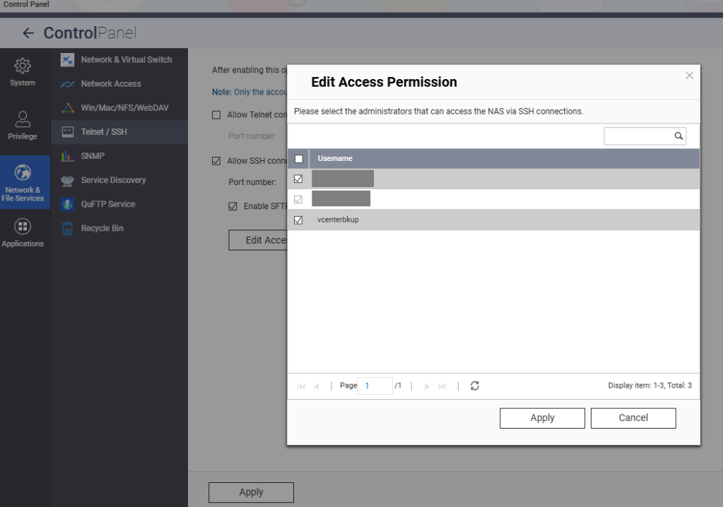
Hit the Edit Access Permission button, and add the service account created earlier, in this example ‘vcenterbkup’.
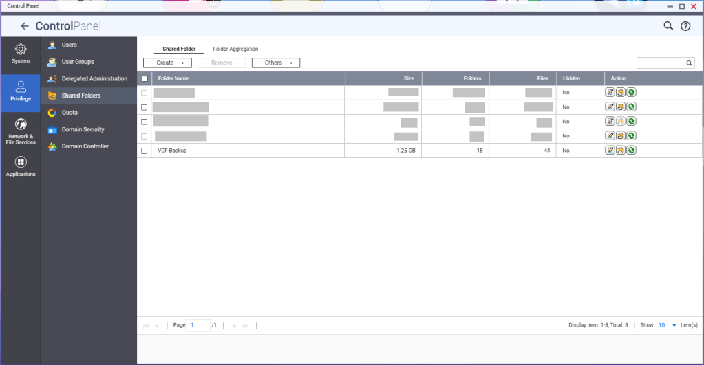
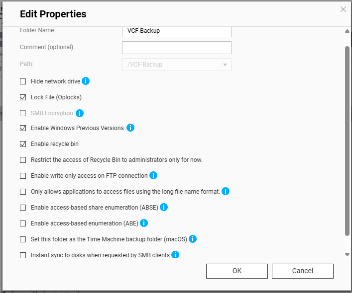
You’ll need to create a shared folder on the NAS, and assign the service account created earlier, in this example ‘vcenterbkup’, with read/write privileges. In this example, I used the folder name of ‘VCF-Backup’.
The size of the folder will depend on your backup strategy for your home lab. One important note, even though the folder path shows as “/VCF-Backup” in the UI, the actual directory will be ‘/share/VCF-Backup/ ‘. This will be important later when backups in the SDDC manager and vCenter are configured.
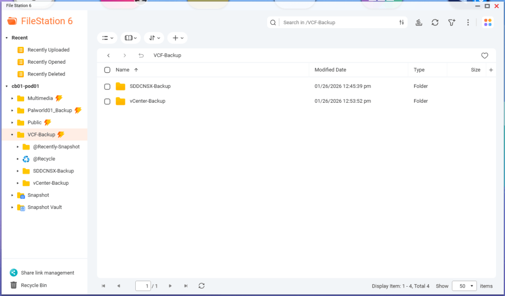
Lastly, I created sub directories inside the VCF-Backup folder. One called ‘SDDCNSX-Backup’, and the other called ‘vCenter-Backup’.
In my next blog, I’ll cover configuring the backups in the SDDC manager, NSXT, and vCenter. NSXT gets configured when the backups are configured in the SDDC manager, however it will need to be tweaked.
I first applied to be a VMware Expert back at the end of 2016 after attending my first VMworld in Las Vegas, and began sharing my experience with the vCommunity through this Captain vOPS blog.
I was lucky enough to join VMware Inc. as an employee in February 2021 to continue working in the Professional Services division working with SLED customers. VMware employee’s had it good back in the day, and we had a pretty robust internal lab environment that I would use for VMware Cloud Foundation Customer projects. I can say with the utmost certainty, that I wouldn’t be where I am today without having a lab to familiarize myself with the VMware product line, both for work and for learning at home. In March of 2025 a little more than a year after the Broadcom acquisition, Broadcom announced that 80% of VMware projects would be sent to Broadcom partners, and the VMware badged PS consultants who were affected by this new strategy, were given the opportunity to transition with them to partners.
The Broadcom partner ecosystem is currently building their own lab environments for VMware consultants, but myself and many others could not afford to wait. Many of us built new home labs with the expectation that we would be able to deploy VCF 9 after Broadcom made the GA announcement late July before Explore. It took the VMUG Advantage team a few extra months to build new backend systems that would adhere to Broadcom’s new VMware subscription and usage reporting system, and many of us were excited to hear that the system finally went live in November. I blogged about how to set that up HERE.
I’ve been deploying VCF for customers through Cloud providers, partners, and VMware itself, going all the way back to the VCF 2.X days. For me, the VMUG Advantage partnership program with the vExpert program, isn’t just a mechanism to get licenses for my VMware home lab. It is a CRITICAL enabler for me to do my job.
It has been a rough year with all of these changes to the VMware brand I once fought for. To that end, I send my heart felt thanks to the VMUG Advantage team, and the vExpert program. They are terrific communities to be a part of. The vExpert program along with its partnership with VMUG Advantage license program has really enabled me to keep doing the job that I love, working with VMware customers, helping them achieve their private cloud goals, as we all try to navigate this new landscape together. A special thanks to Corey Romero and Eric Nielsen for keeping these communities alive before, during, and after the transition.
If you’ve been following along in this home lab series, in my previous blog, I finished my VCF 9.0.1 deployment to my 4 MINIS FORUM MS-A2s HERE.
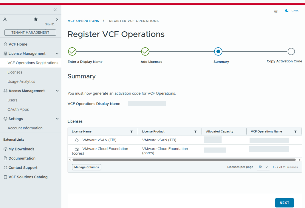
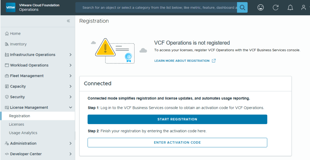
With Broadcom’s VCF 9, we are now required to configure usage reporting. This process is pretty straight forward. Click on the [START REGISTRATION] button, and you’ll be redirected to the Broadcom portal for authentication.
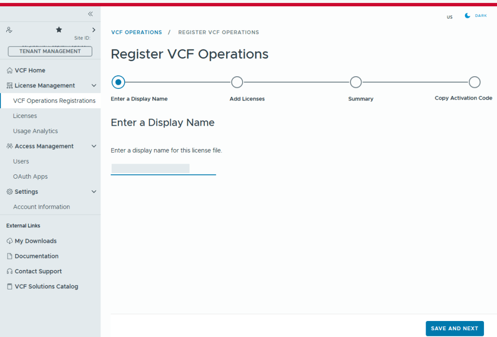
You’ll need to enter a display name for this license file. It could be representative of the environment where used.
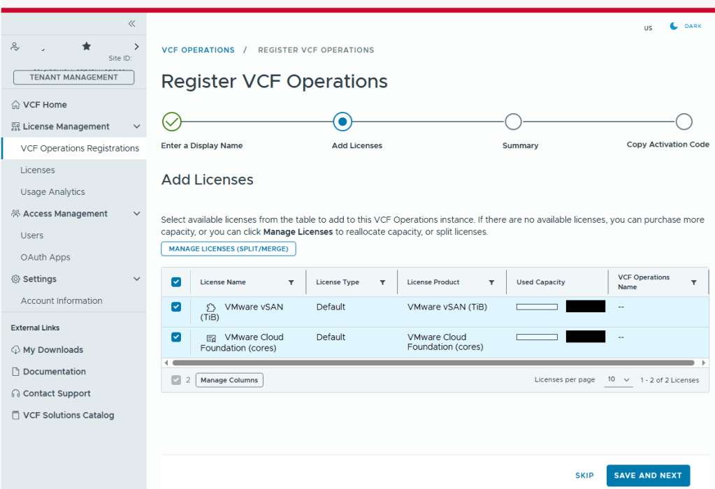
Select the licenses needed for the environment..
Validate the selection.
Now we just need to copy the activation code.
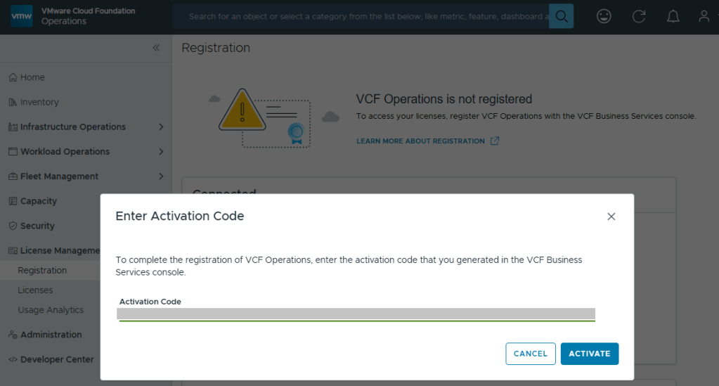
Back in VCF Operations, we now click the [ENTER ACTIVATION CODE] button to paste in the code.
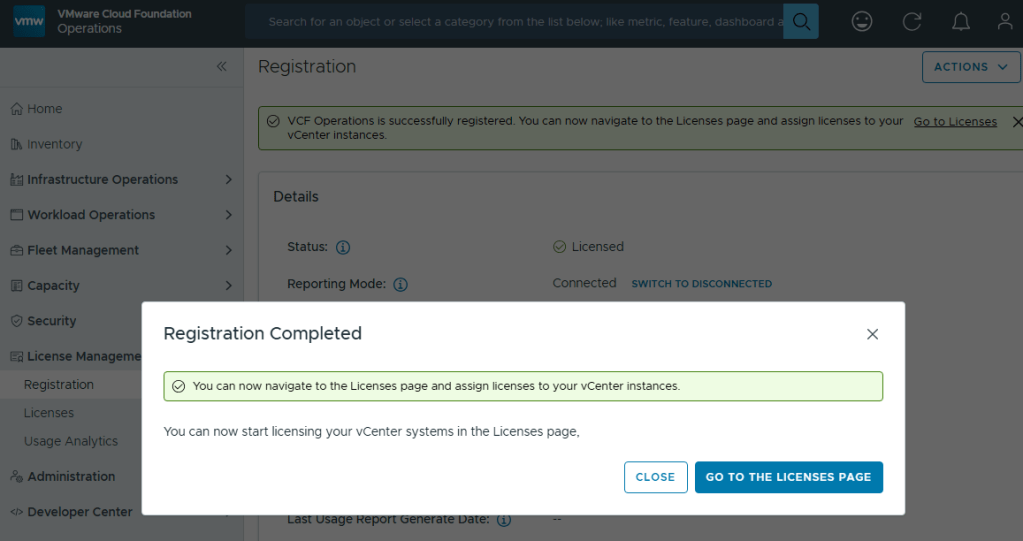
With your Activation Code ready, now you can activate.
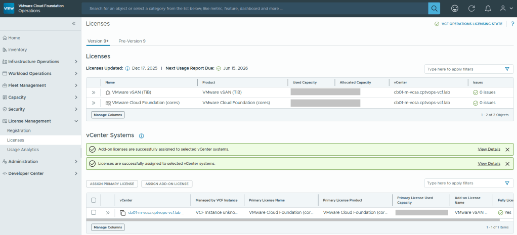
Now your licenses will be available to apply to vCenter (PRIMARY LICENSE) and vSAN (ADD-ON LICENSE).
But wait… There’s More!
I am rather surprised that we have to apply the download token twice considering it’s a requirement to download the bits for the installation, especially in a world where we are constantly striving to automate all the things. Maybe Broadcom’s VCF Engineering division just overlooked this simple quality of life automation task to copy said download Token from the Cloud Installer, and import it to VCF Operations?
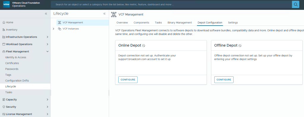
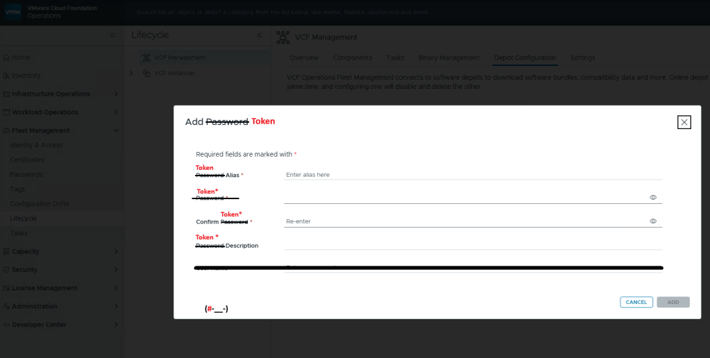
You’ll want to add your download token again to VCF Operations: Fleet Management ->Lifecycle ->Depot Configuration
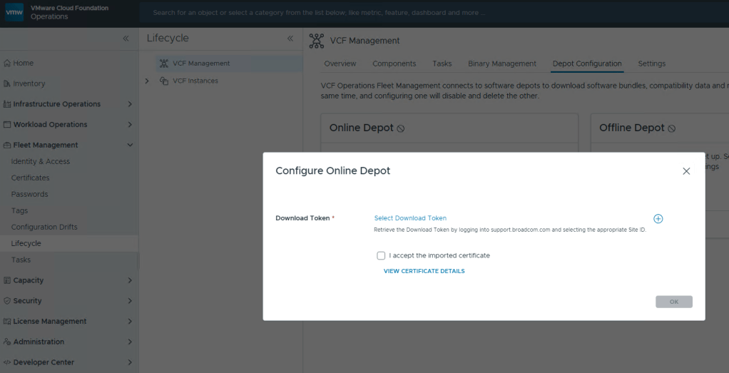
This looks oddly familiar for creating a credential file for VCF (Aria) Operations Integration. Click the plus icon.
Well that’s… disappointing.
I fixed it for you, Broadcom.
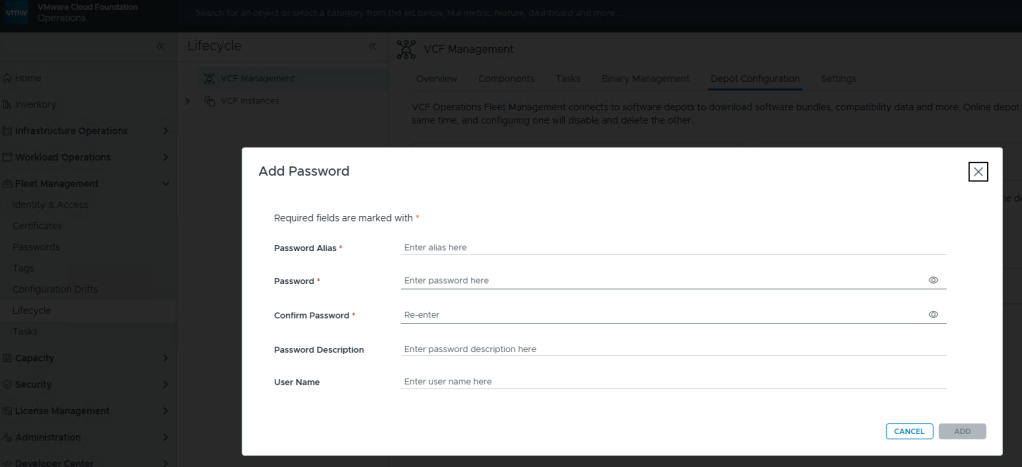
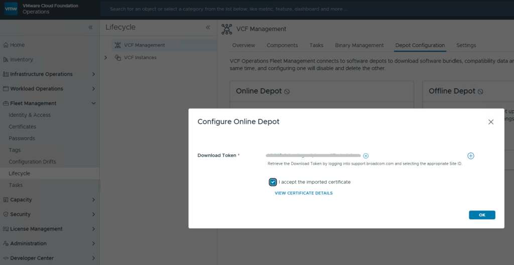
Just like you would create a credential file, here you add your download token where you’d add your password, and click [ADD].
Now just select your Download Token and click [OK].
In my previous post, I walked through the process of getting the VMUG Advantage token configured in the Cloud Foundation Installer, to establish the connection to the online depot and download the VCF bits, HERE. This post assumes those bits have all been downloaded successfully.
Before continuing with your VCF 9 home lab deployment, or even a production deployment, be sure to check out this post HERE, where I cover the updated password requirements for VCF, and how missing those requirements will cause the deployment to fail.
For a VCF 9 home lab running on hardware that’s not part of the VMware HCL, it will be necessary to bypass the vSAN ESA precheck during VMware Cloud Foundation (VCF) deployment using the Cloud Foundation Installer. If compatible vSAN ESA hardware is not available in your home lab, the deployment fails during the HCL validation phase. To bypass this, log in to the VCF Installer and append the following configuration parameter to the following /etc/vmware/vcf/domainmanager/application-prod.properties file:
Next, you’ll either need to restart the the appliance, or you can just restart the service with the following:
systemctl restart domainmanager
Time to start the VCF 9 deployment.
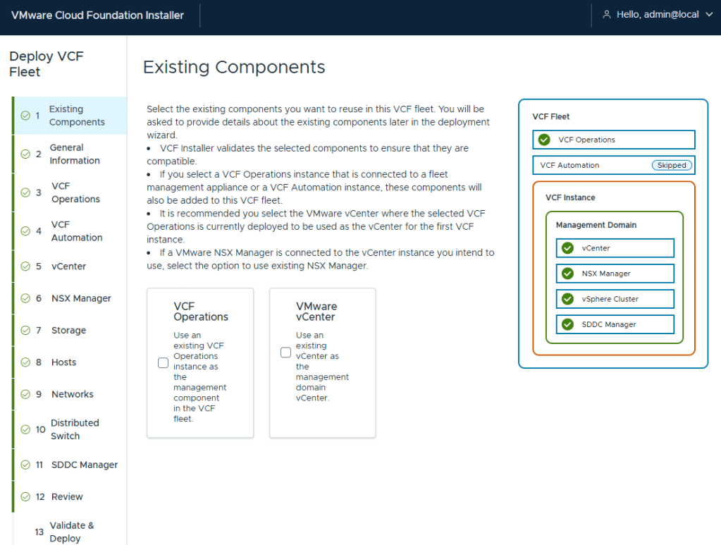
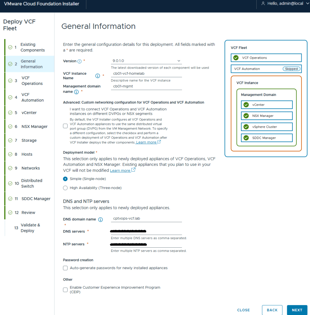
I’ve been deploying VCF for customers since the 2.X days, so I have mixed feelings about this new wizard. However, I must say I do enjoy not having to fill in multiple deployment workbooks. I am deploying a greenfield VCF home lab, so I do not have existing components
I elected to do a simple deployment for my homelab. I did notice through testing that the Installer will hallucinate if one of the NTP servers is not reachable. Later on during the pre-check validations, I saw error messages stating the NTP value was null. Probably my favorite was when it hallucinated NTP values that I did not configure, but said that it couldn’t reach them (duh). My only indication of the actual problem was that the pre-check failed when it couldn’t validate the ESX hosts connection to the second NTP and DNS server. I wonder how much vibe coding the VCF devs were doing that day?
I hadn’t deployed my second domain controller yet that I would also use as my second NTP source, and was hoping that I could set it during the Core VCF deployment, and deploy the server after. I ended up just deleting the second DNS and NTP server address in the Installer. I’ll just add it later. I left them configured on the ESX hosts.
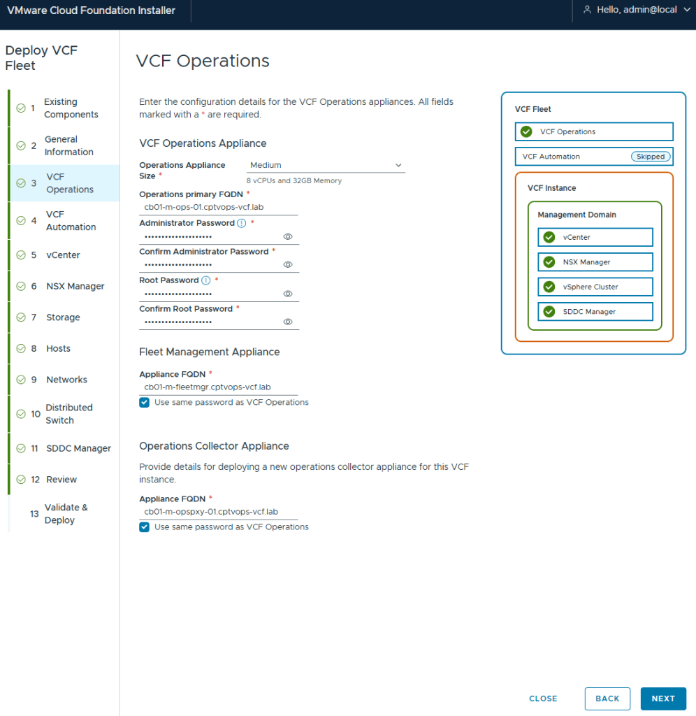
Deployment for VCF (Aria) Operations and Fleet Management Appliance (Aria Suite LCM)
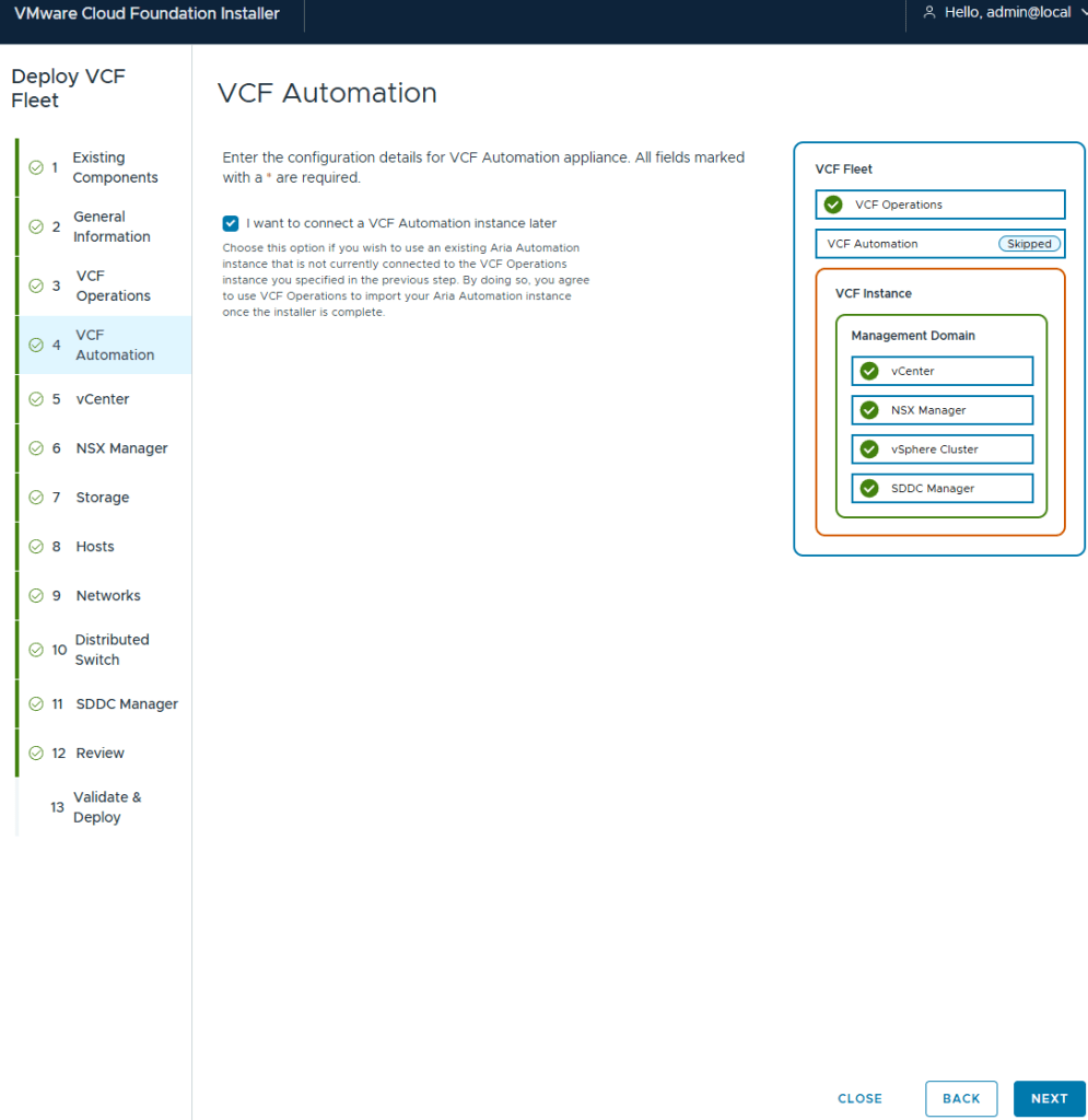
I elected to not deploy VCF (Aria) Automation. I’ll deploy this after.
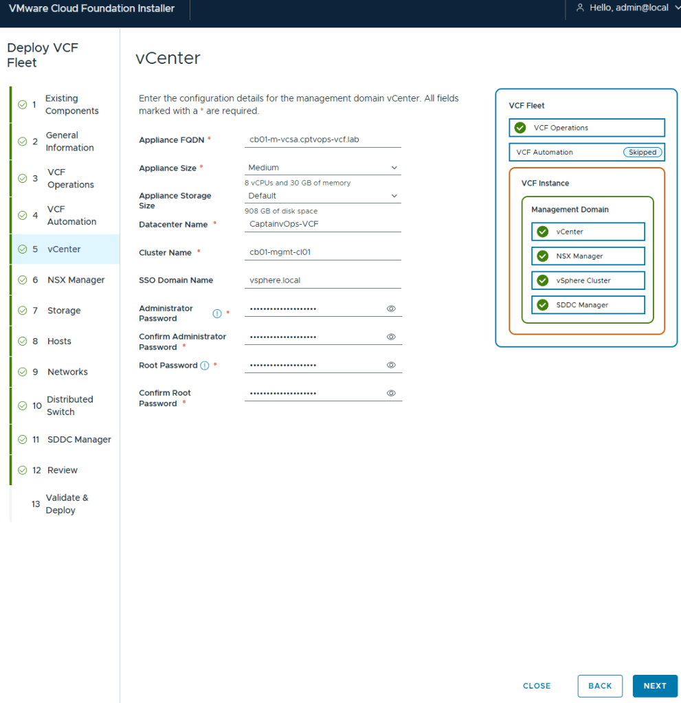
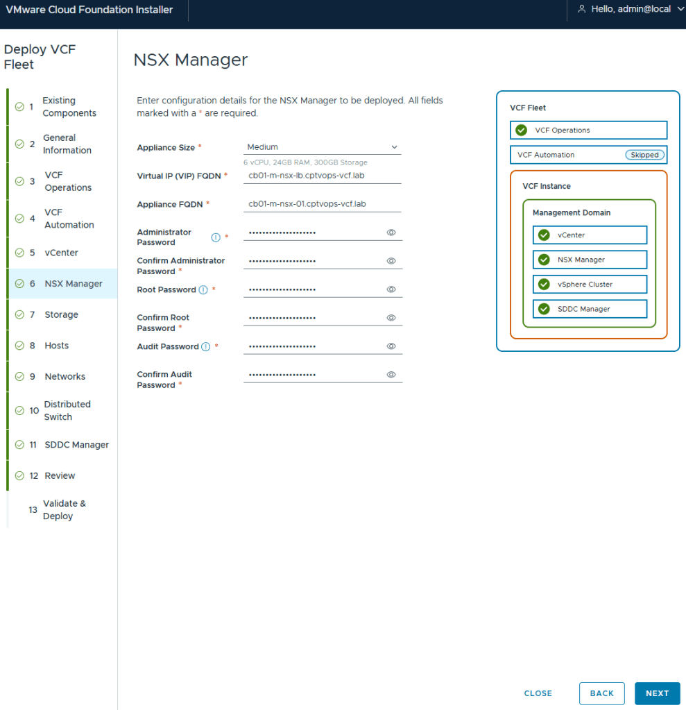
I deployed my management vCenter using the medium size to avoid the smaller appliances performance issues.
Even though the “simple deployment” was chosen, you are still required to define a Virtual IP for NSX.
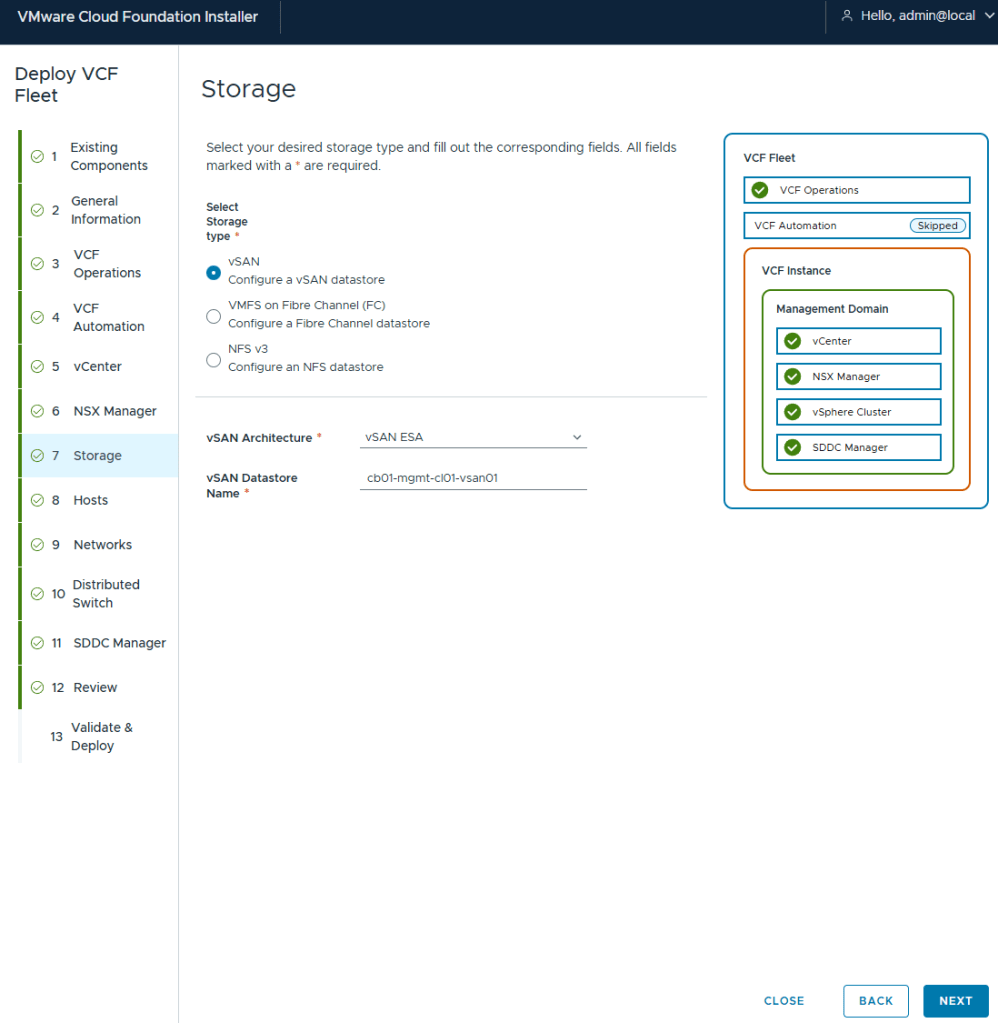
Out of all the VMware home labs I have built, this is my first using vSAN, but I wanted to try out ESA. In the past I avoided vSAN just because in certain situations it made host maintenance painful.
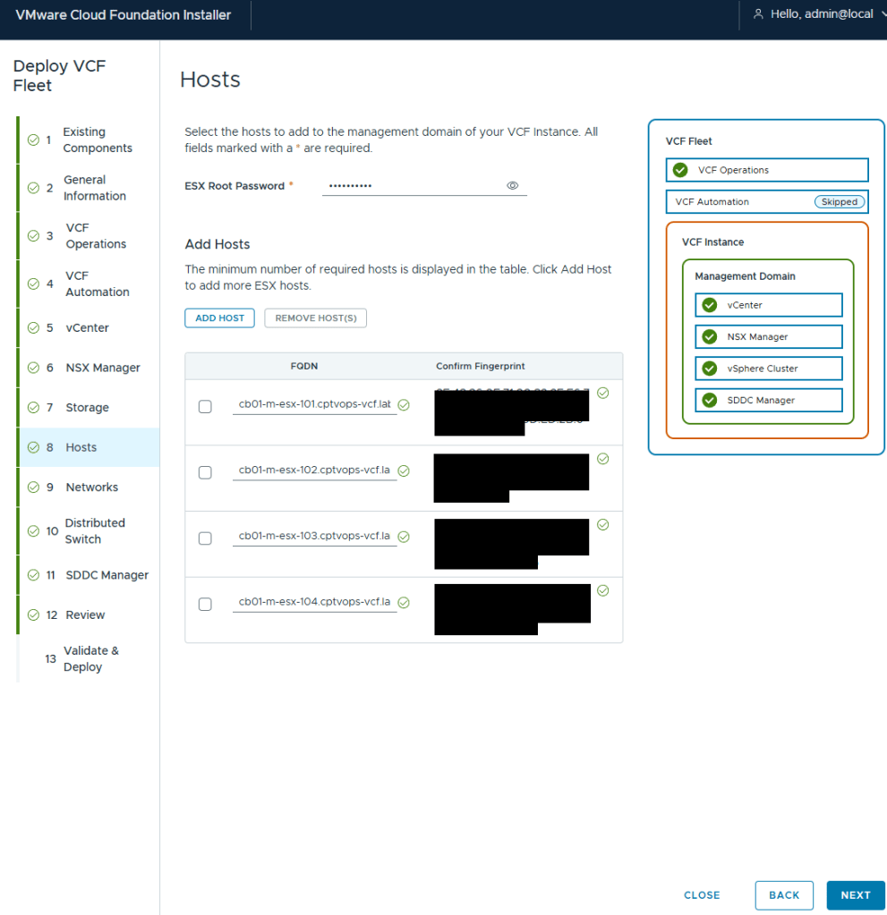
I’ve got my 4 MINISFORUM MS-A2 hosts added.
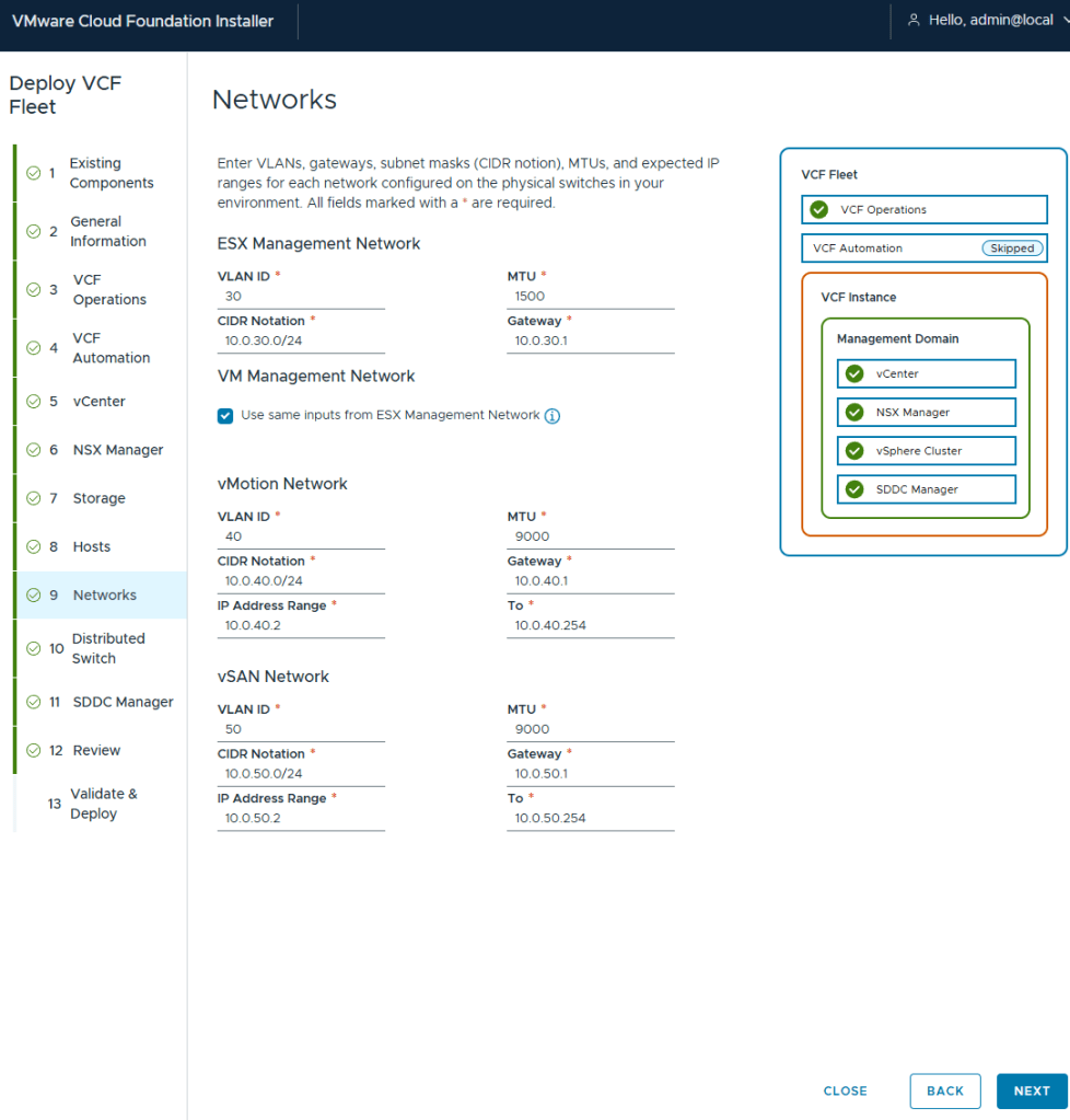
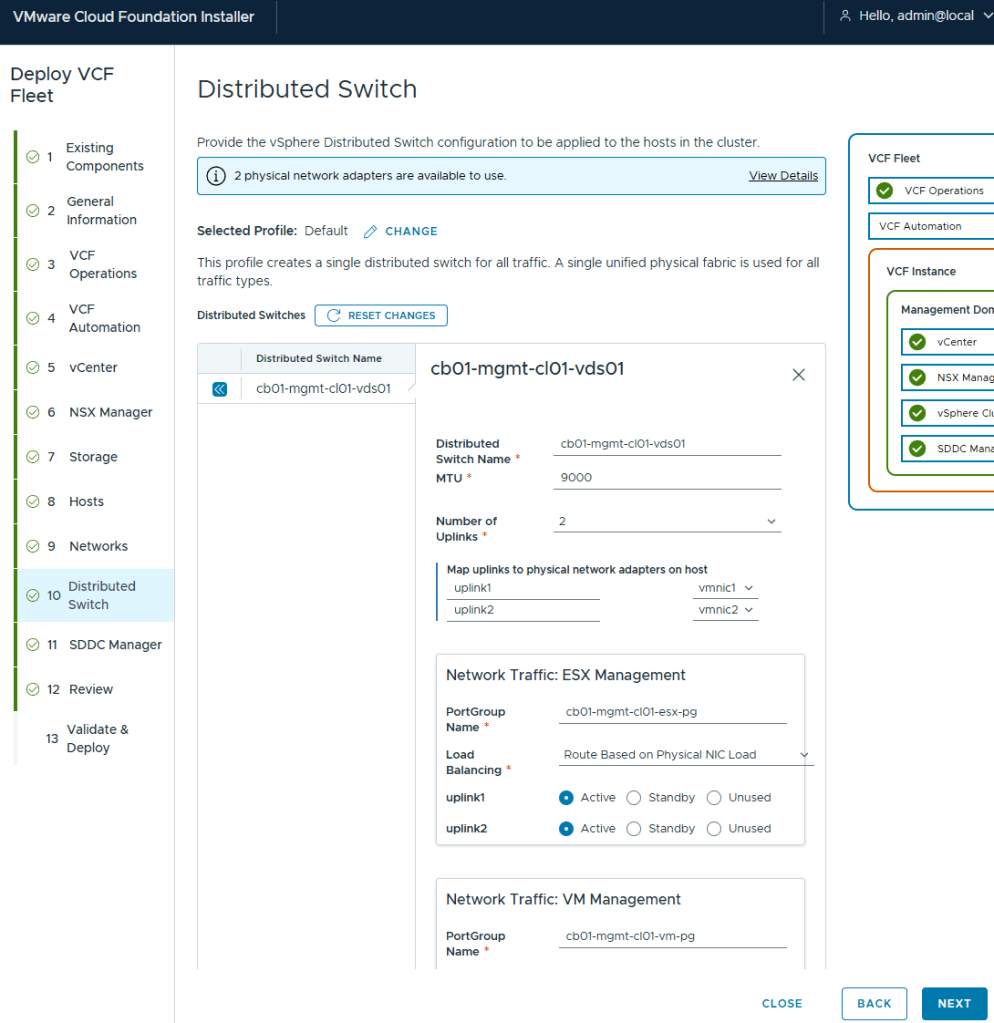
I elected to keep my deployment simple in my home lab, and have my management VMs share the same network as my ESX hosts.
I chose the Default virtual distributed switch config
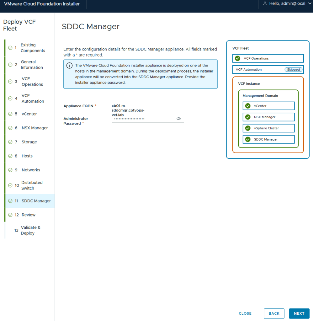
If you remember my previous post HERE, I talked about what will happen on this screen if you did not use a 15 character password for the local user (admin/Administrator).
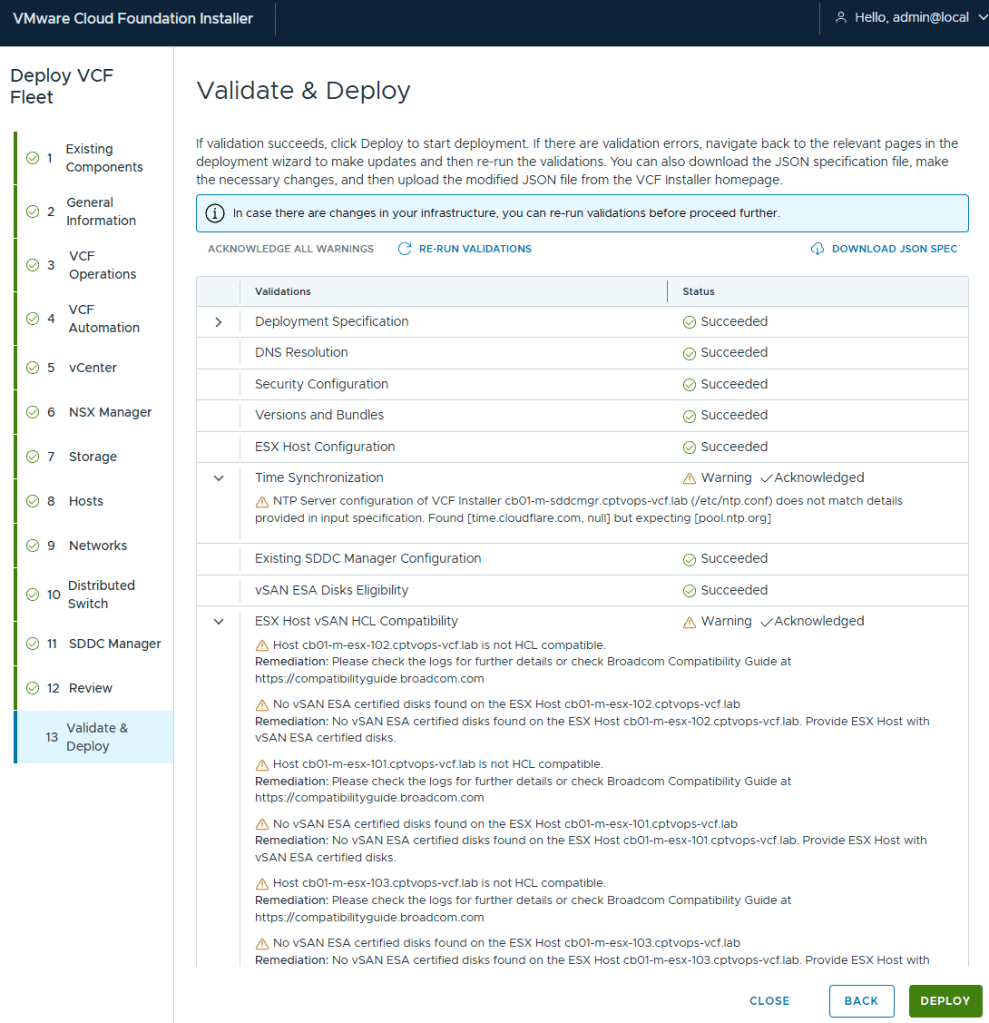
As expected, the pre-check validation returned a WARNING on the vSAN ESX Disks Eligibility for not being on the HCL. This needs to be Acknowledged before the [DEPLOY] button becomes available.
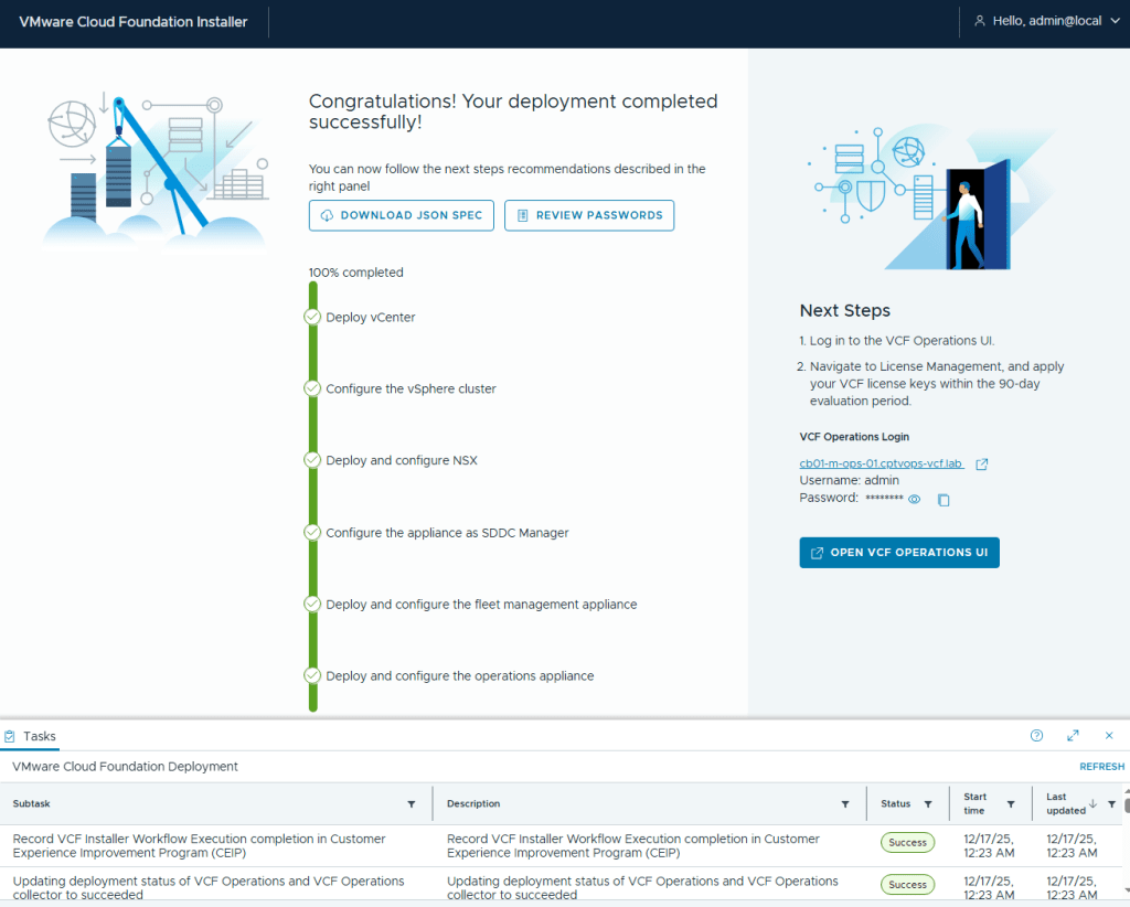
I kicked off the VCF 9 deployment in my home lab at roughly 5:03pm. The deployment finished about 7 hours later (12:23AM to be exact). Honestly, it was the NSX OVA deployment that took roughly 6 hours to complete. The VCF Fleet Manager, VCF Operations, and VCF Ops collector deployed around an hour I believe.
In my next blog, I’ll run through getting VCF Operations connected to the Broadcom Cloud Services portal to activate my licenses in my home lab.
In this blog, I’ll go over the basic deployment of the VMware Cloud Foundation Installer appliance (formally VCF Cloud Builder) OVA, because there’s a new ‘feature’ that will trip you up if you’re not careful.
We’ve all installed OVAs before, but for the Cloud Foundation Installer OVA, there was something that I wanted to call out.
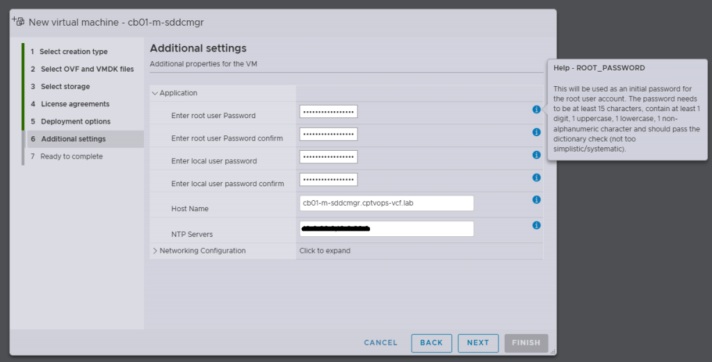
Specifically, when you’re deploying the OVA, be mindful of the new password requirements as they have changed. Previous versions of VCF through VCF 5.x, did not require a 15 character password. Apparently the quality control folks over in the VCF Division at Broadcom also forgot about this, because you can enter an 8 character passwords here, and the OVA deployment will continue as normal.
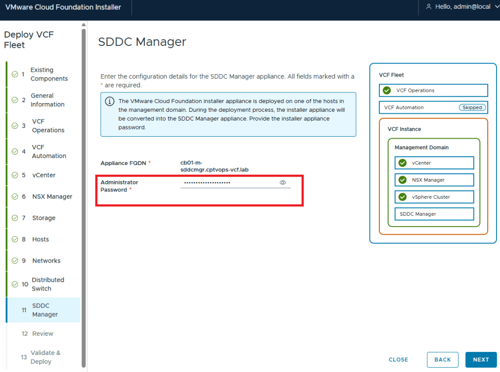
Why does this matter, well if we fast forward here a little bit, and get to where we are in the VMware Cloud Foundation deployment wizard on Step 11, you are again asked for the Administrator Password (local user). If you did not use at least a 15 character password during the OVA deployment, the wizard when you click [NEXT] will state that the Administrator password is incorrect . It doesn’t warn you that it is too short. So after a couple of tries, you will get kicked out of the wizard and back to the Cloud Foundation Installer login page, unable to log in because the local user (admin account) is now locked… I first observed this behavior during a customer deployment of 9.0, and found that the ‘feature’ is still there in the 9.0.1 I deployed for my home lab.
One of the things that I had been waiting for were the VMware Cloud Foundation 9 subscription licenses for VMUG Advantage members and the vExpert community of bloggers and SMEs. VMUG Advantage Home Lab License Guide During the week of November 17th, it was announced that the download tokens are now available for the VMUG Advantage Members who passed their VCF 9 certifications.
This post assumes that you have already deployed the VCF Installer, and are ready to get those VCF 9 bits downloaded to your home lab like a typical production environment would.
Your VMUG Advantage account email has to be the same as the one that you use with your VMware by Broadcom certifications.
After you authenticate, there’s a good chance that your session has been redirected to the Broadcom Support Portal. Past the above URL back into your browser and hit enter…
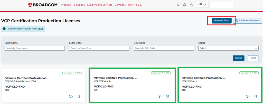
You should have now arrived at the special VMUG Advantage portal and see the VCF Certification Production Licenses in the upper left of the screen like so:
I have already requested my licences for VCF, and thus have a badge and a cloud download button on the green highlighted boxes. If you do not see those, then you would see a blue request license button. This post assumes you already have done this.
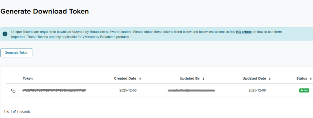
5. In the top right of the window, you see a blue “Generate Token” button. Click it. 6. On the next screen, you should see the download token needed for the VCF Installer. Copy it.
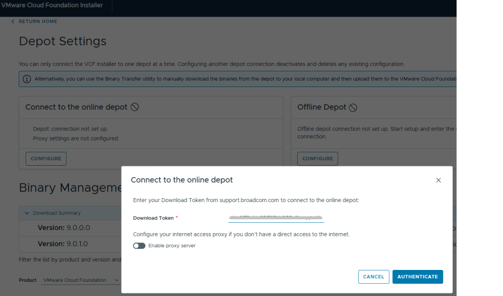
7. Log into the VCF installer appliance. 8. Go into Depot Settings, and click ‘Configure’ on the Connect to the online depot. 9. Paste the download token and click the blue ‘Authenticate’ button.
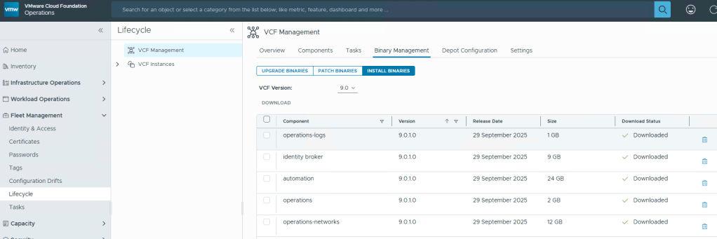
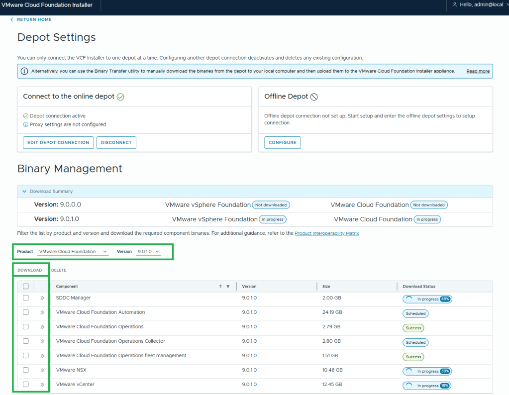
10. Assuming your VCF Installer can reach the internet and depot, a connection will be established. 11. In this example, I want to download the Product “VMware Cloud Foundation” and Version “9.0.1.0”. 12. Select all the bits desired for download, and then click the ‘DOWNLOAD’ link.
VMware by Broadcom has made this process more difficult. All of the required bits for installation used to be included with the Cloud Builder appliance that was available for VCF 5 and older versions. Now there’s an extra step to download the bits, but I’m sure that was a feature of the required download token. More complexity.
In this post I’ll cover the basic ESX host prep needed for VMware Cloud Foundation. This post assumes that ESX 9 has already been installed. This post also assumes these are brand new hosts that have not been used for vsan before.
Configure the ESX Host basic network settings via the DCUI
Open the DCUI of the ESX host.
Open a console window to the host.
Press F2 to enter the DCUI.
Log in using the esx_root_user_password.
Configure the network.
Select Configure Management Network and press Enter.
Select VLAN (Optional) and press Enter.
Enter the VLAN ID for the ESX Management Network and press Enter.
Select IPv4 Configuration and press Enter.
Select Set static IPv4 address and network configuration and press the Space bar.
Enter the IPv4 Address, Subnet Mask and Default Gateway and press Enter.
Here I would also disable IPv6 if not in use.
Select DNS Configuration and press Enter.
Select Use the following DNS Server address and hostname and press the Space bar.
Enter the Primary DNS Server, Alternate DNS Server and Hostname (FQDN) and press Enter.
Select Custom DNS Suffixes and press Enter.
Ensure that there are no suffixes listed and press Enter.
Press Escape to exit and press Y to confirm the changes.
Reboot the host.
Repeat this procedure for all remaining hosts.
Configure the Virtual Machine port group on the standard switch
In a web browser, log in to the ESX host using the VMware Host Client.
Click OK to join the Customer Experience Improvement Program.
Configure a VLAN for the VM Network port group.
In the navigation pane, click Networking.
Click the Port groups tab, select the VM network port group, and click Edit Settings.
On the Edit port group – VM network page, enter the VM Management Network VLAN ID, and click Save.
Repeat this procedure for all remaining hosts.
Configure NTP on the Host(s)
In a web browser, log in to the ESX host using the VMware Host Client.
Configure and start the NTP service.
In the navigation pane, click Manage, and click the System tab.
Click Time & date and click Edit NTP Settings.
On the Edit NTP Settings page, select the Use Network Time Protocol (enable NTP client) radio button, and change the NTP service startup policy to Start and stop with host.
In the NTP servers text box, enter the NTP Server FQDN or IP Address, and click Save.
Click the Services tab, select ntpd, and click Start.
Repeat this procedure for all remaining hosts.
Regenerate Self-Signed Certificate on ESX Hosts.
In a web browser, log in to the ESX host using the VMware Host Client.
In the Actions menu, click ServicesEnable Secure Shell (SSH).
Log in to the ESX host using an SSH client such as Putty.
Regenerate the self-signed certificate by executing the following command: #: /sbin/generate-certificates
Reboot the ESX host.
Log back in to the VMware Host Client and click ServicesDisable Secure Shell (SSH) from the Actions menu.
Repeat this procedure for all remaining hosts.
I don’t know why, but every customer engagement that I have been on, these steps get overlooked. This is probably the simplest part to preparing your data center for VCF. VMware by Broadcom also has documentation with these exact steps located here: Preparing ESX Hosts for VMware Cloud Foundation or vSphere Foundation
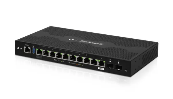
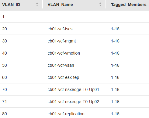
Below is the basic network Topology and vlan config for my new VMware Cloud Foundation home lab. For my home network, I had replaced my off the shelf consumer wifi router a few years ago, and purchased a Ubiquity EdgeRouter 12 so that I could have vlans for my VMware Home lab, that lasted me from vSphere 6 to vSphere 8.
On this router, I have defined and hung the vlans off from the built in virtual switch (192.168.X.1).
vlan (10.0.X.1)
Description
20
iscsi storage straffic
30
Management
40
vmotion
50
vsan
60
ESX TEP
70
NSX Edge T0 Uplink01
71
NSX Edge T0 Uplink02
80
Replication
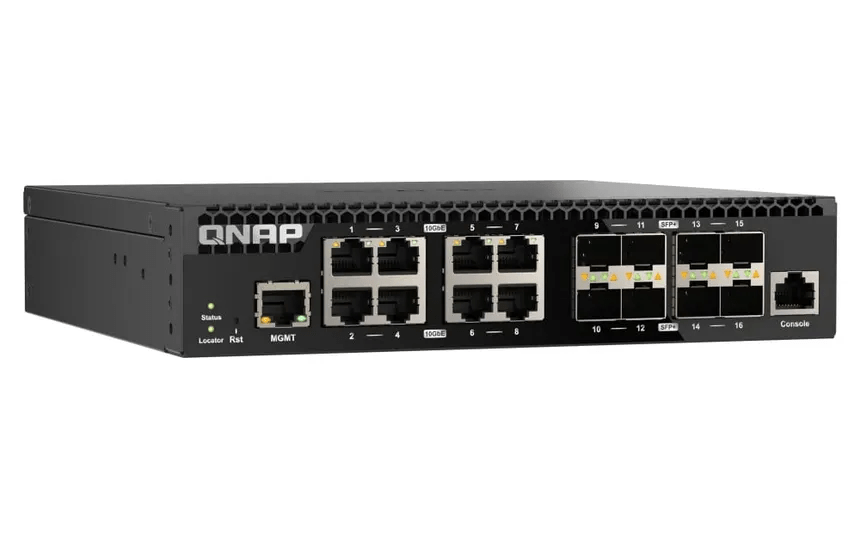
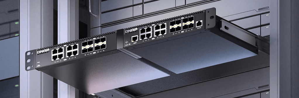
As detailed in my VCF 9 Home lab BOM, I chose to go with the QNAP (QSW-M3216R-8S8T-US) Layer 2 for my TOR switch. This Layer 2 managed switch supports 10G on the standard ethernet ports and on the SFP+ ports, giving me lots of options for connectivity.
I can also mount two of them side by side in a standard 19 inch width rack offering more space save opportunities for future home lab expansion.


You must be logged in to post a comment.