This is a continuation of deploying VMware Cloud Director 10. In my last post, I walked through configuring the vSphere lookup service, and adding the vCenter (here). In this post I’ll go over adding a Provider Virtual Data Center (PVDC).
Adding a PVDC
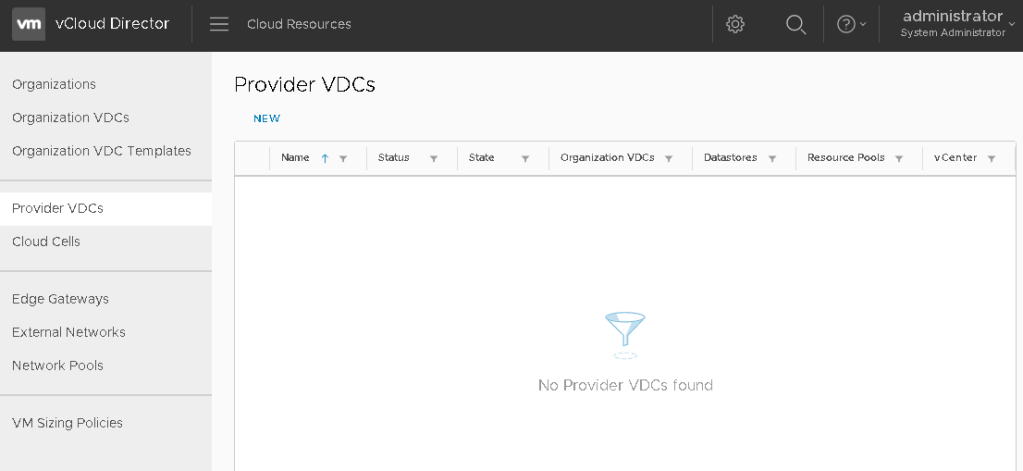
Log into the vCD provider interface, and switch to the Cloud Resources view by clicking the menu to the right of vCloud Director logo. Select the Provider VDCs option in the menu on the left, and then “NEW” link to begin.
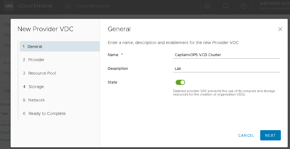
On page 1, you’ll have to fill in some general information about the PVDC. Give it a name and description meaningful to the resources the PVDC will be connected to. In this example, I am connecting to my home lab. Click NEXT.
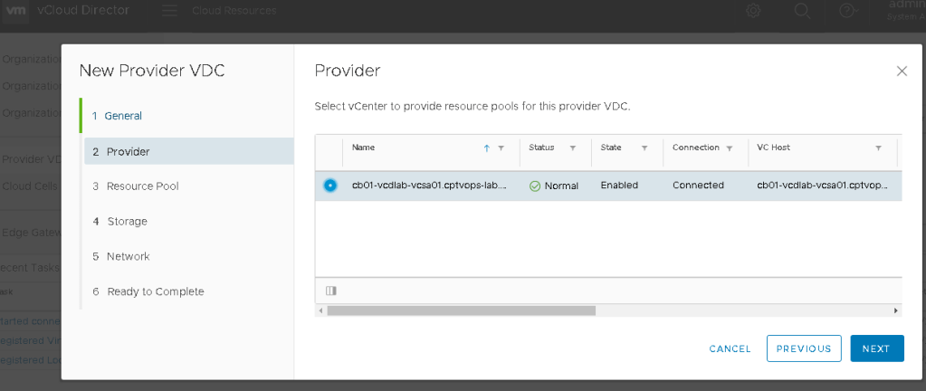
On page 2, select the vCenter and click NEXT.
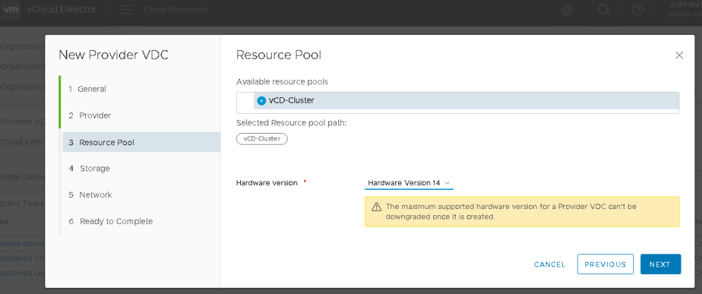
On page 3, you’ll see the available resources. This would be for both compute and storage. In this example I am using a lab, so I only have one available. Hardware compatibility is also configured here for the future tenants deployed to this PVDC. Click NEXT
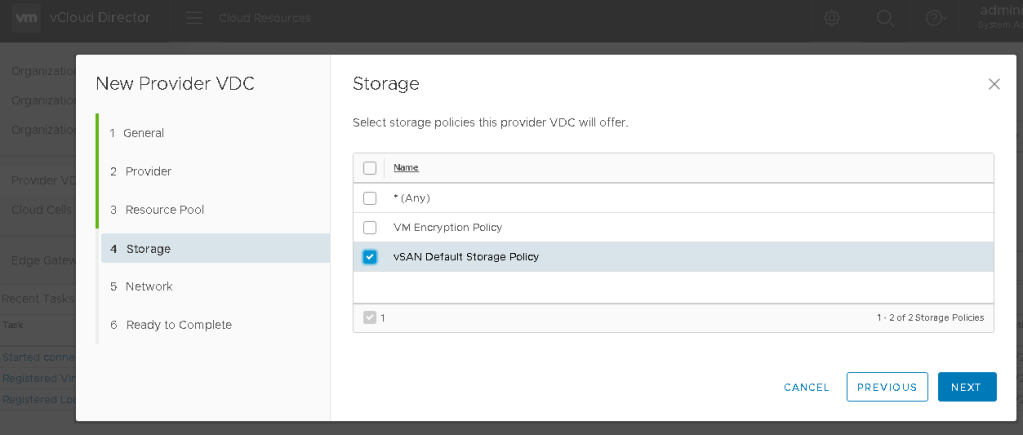
On Page 4, the available storage policies configured in the vCenter that the tenants would use in this PVDC, will be available for selection here. Click NEXT.
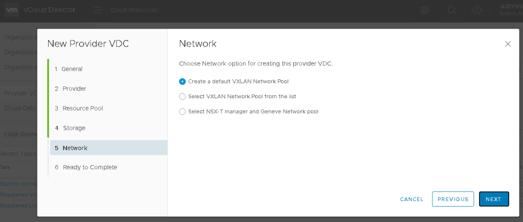
On Page 5, your mileage may vary depending how your environment is configured. In my lab example, I have chosen the default selection. Click NEXT.
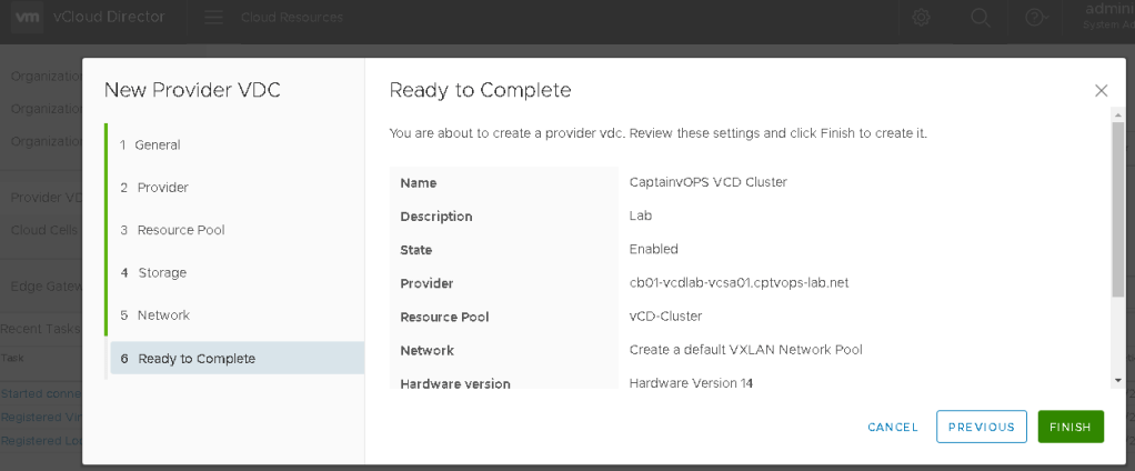
On page 6, you are presented with a confirmation of the selected config. Make any adjustments, and click FINISH.
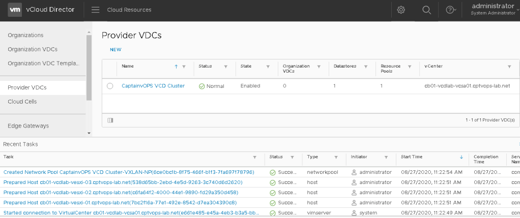
Be patient as it can take some time to build the PVDC. Just monitor the recent tasks for task progress and completion. The end result should show a “Normal” for a status under the configured Provider VDCs.
At this point, the provider side configuration is almost complete. We still need to configure the public facing address. If this were a production deployment, we also find it necessary to configure a VIP/load balancer to place in front of the VCD appliances to handle traffic load. For production deployments there would also be the need to setup signed certificates for the appliances.
In my next blog I’ll go over configuring the public address.
This is a continuation of deploying VMware Cloud Director 10. In my last post, I walked through deploying additional appliances for database high availability (here). Today we will add the vSphere lookup service and the vCenter.
Configuring the vSphere Lookup Service
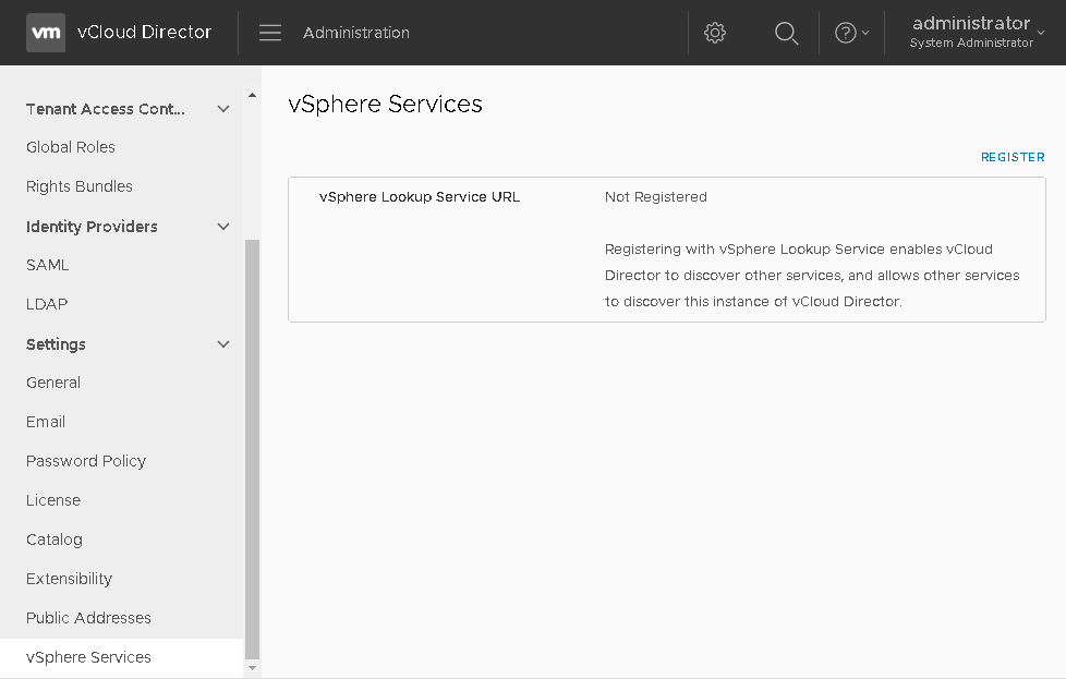
Log into the vCD provider interface, and switch to the Administrator view by clicking the menu to the right of vCloud Director logo. Then under Settings on the right select vSphere Services.
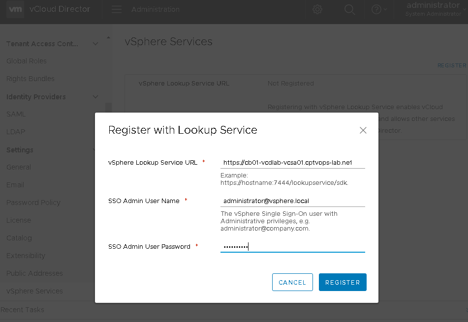
After clicking the “REGISTER” link in the upper right, we’ll be able to add the lookup service URL link for the vCenter we’ll connect to a little later. Registering with vSphere Lookup Service enables vCloud Director to discover other services, and allows other services to discover this instance of vCloud Director.
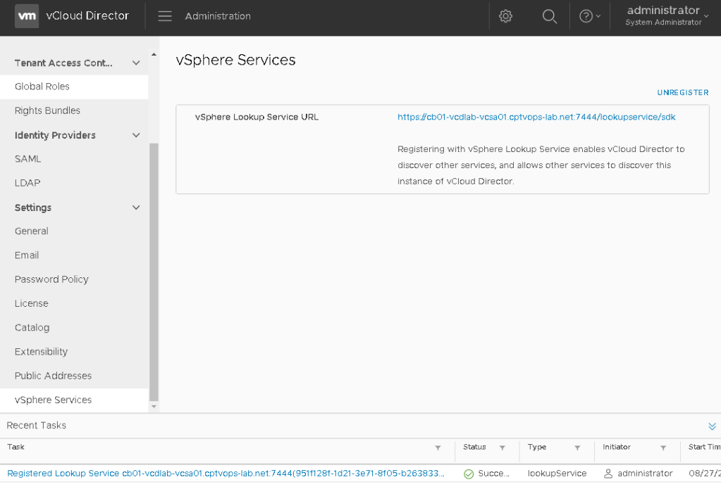
Once all of your information is added, click the Register button. Watch the task for successful completion below.
Adding the vCenter
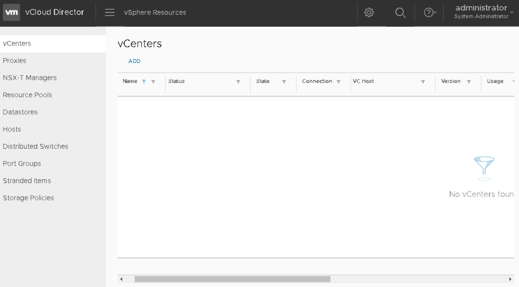
Click on the menu again to the right of vCloud Director logo, and select the vSphere Resources. On the top menu option to the right “vCenters”, click the Add button.
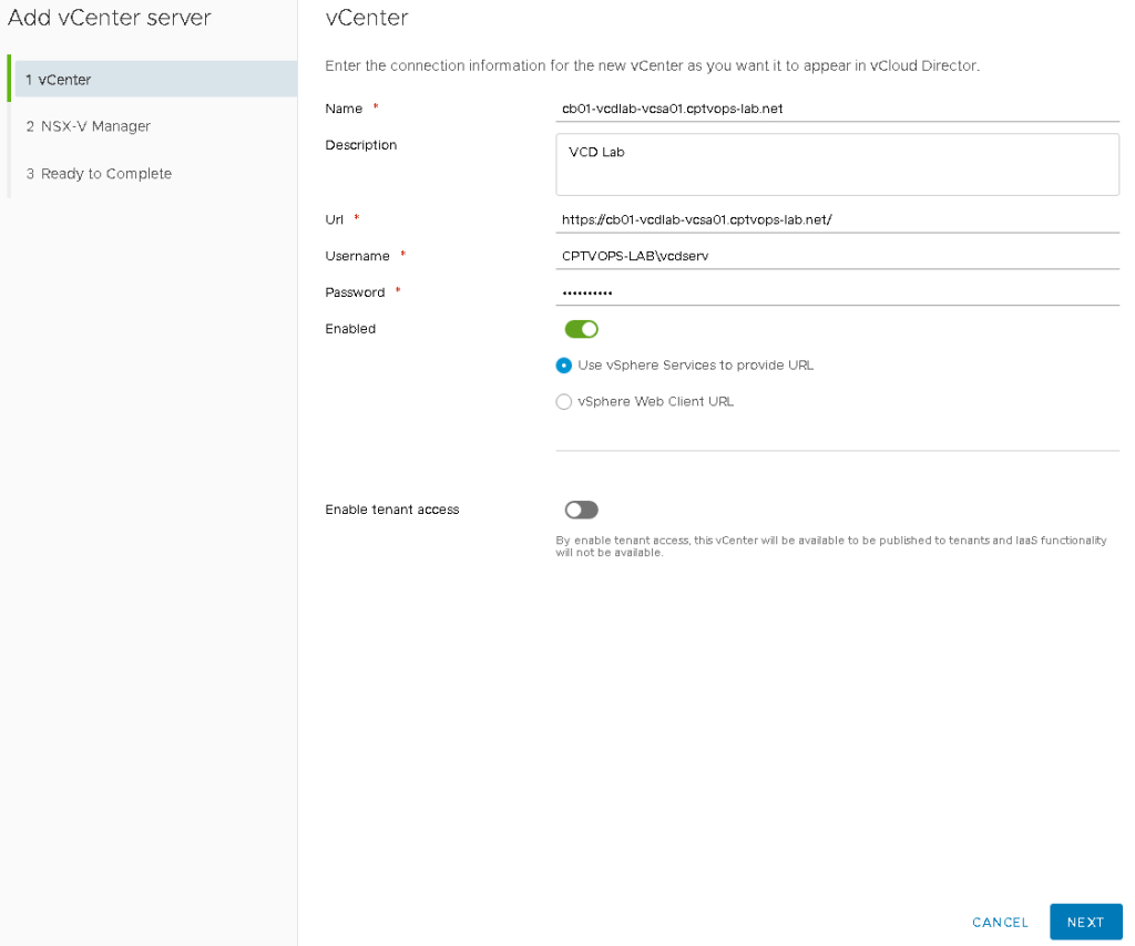
On page 1 of the wizard, fill in the required information for the vCenter. We already configured the lookup service, so we can leave that option selected here to provide the URL. Click next.
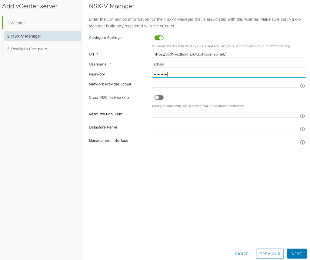
On page 2, add the information for the NSX-V appliance. Click Next.
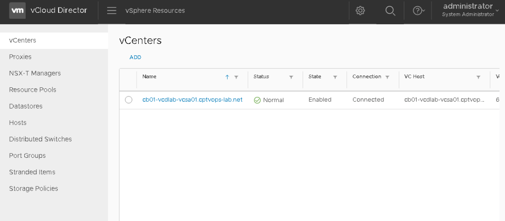
Click finish, and then wait for the vCenter to connect and show a status of Normal.
Now that we have the vCenter connected, we can proceed to setting up and configuring the Provider Virtual Data Center (PVDC). This is required in order to make the vCenter resources such as compute and storage available to tenants. I’ll go over configuring the PVDC in the next blog.
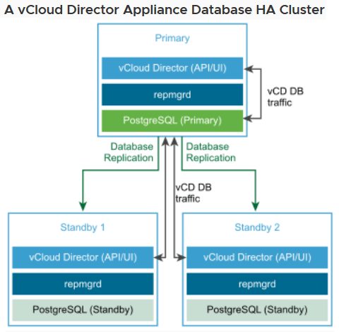
In my last blog, I walked through the process of Deploying the vCloud Director Appliance v10, and today’s blog will feature the process of deploying two additional standby appliances to create an HA database configuration for vCD. To get an idea of what that architecture would look like, I’ll rip this excellent diagram from VMware’s own documentation.
Deploying additional appliances are pretty straight forward, so lets get started.
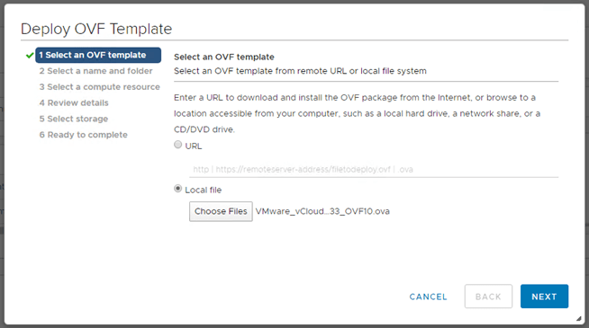
1 – Find and upload the OVF for vCD.
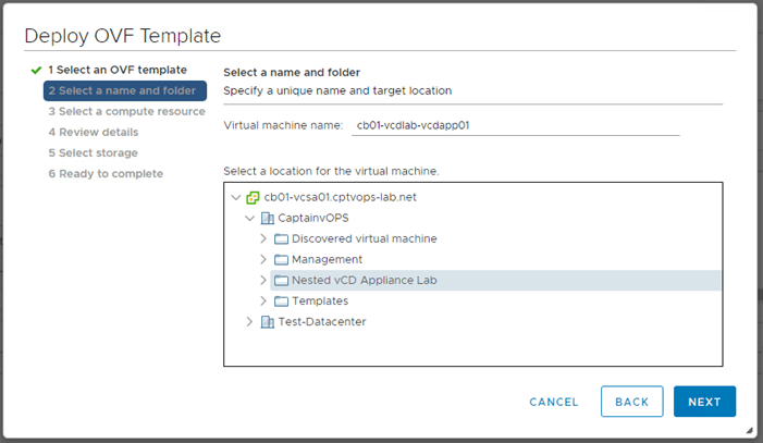
2 – Name the VM, select the datacenter and virtual machine folder.
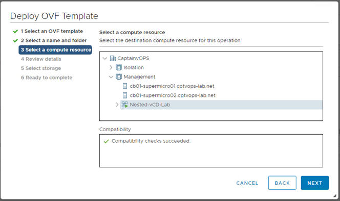
3 – Select the compute cluster
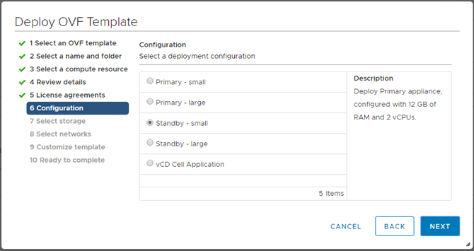
4 – The primary appliance has already been deployed. It is important to note that the same size standby appliance has to be deployed. Because our first primary appliance was deployed as small, so to shall the standby appliance. VMware’s sizing guide and be found here.
5 – Select desired storage disk format and storage where the appliance will reside.
6 – Configure the networks for each network interface, keeping in mind that they will be in reverse order as discussed before.
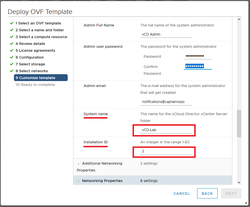
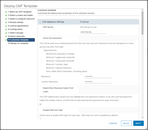
7 – Fill out the template customization page just like before. Remember all fields including the administrator email are required.
Note: – Be sure to use the same “System name” that was used for the original vCD primary appliance deployment. – For the “Installation ID” section, make sure this value reflects increases with the number of appliance being deployed. In this demonstration I am deploying the 2nd and 3rd appliances, so the installation IDs would be 2 and 3 respectively.
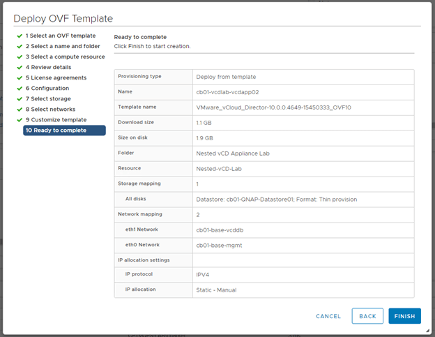
8 – On the summary page, verify the deployment and click finish.
9 – Before starting the appliance, it may be a good idea to take a snapshot. Once the appliance has been started, and the configuration scripts attempt to run and fail, the appliance will need to be redeployed. I’d also take a snapshot of the primary appliance, to roll back any failed attempts to join.
10 – Once you have started the appliance, watch for the “Guest OS Initialization Script”. This should take a couple of minutes to run in order to be successful. If it runs for less than 10 seconds, then there was a problem and the appliance will need to be redeployed.
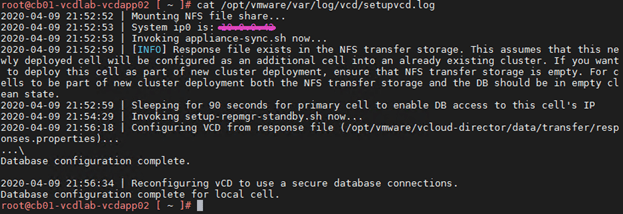
11 – After the appliance boots, look at the /opt/vmware/var/log/vcd/setupvcd.log to validate a successful cluster join. This log can also be used if the appliance deployment failed.
A successful join would look something like this:
12 – Now deploy the 3rd standby appliance using steps 1 through 11.
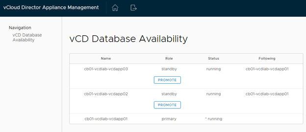
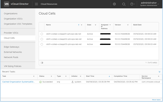
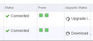
13 – Once the 3rd appliance has been deployed, it would be a good idea to log into the primary appliance’s 5480 page to validate the health of the new DB cluster.
15 – Here we can also see the state of the cloud cells.
End – I’ll finish this blog post here. In my next blog, I’ll walk through the steps of configuring the newly deployed vCloud Director environment. Stay tuned.
Prior to this blog post, blogged and walked through the steps of creating a NFS linux server using CentOS 7. You can find the link to that blog post here.
The VMware Cloud Director (vCD) platform is primarily used by service providers, as a cloud offering for their customers. Back when I worked for a service provider, the bulk of my experience came from the version 8.x days, when vCD was a software package to be installed on a Linux VM. Fast forward a few years, and I’ve started deploying vCD 9.7 and vCD 10 appliances for VMware customers, part of Professional Services engagements for VMware that I’ve been working on. Interestingly enough, both customers were not cloud providers, but had specific use cases that vCD achieved.
The vCD appliance deployment certainly is not as clean as other appliances like vCSA and vROps, and I’ve found there to be a few gotchas that can lead to a failed appliance deployment.
Deploying the vCD appliance
Like most appliance deployments, we’ll deploy an ovf template.
2. Name the virtual machine, and select desired deployment datacenter and VM folder location.
3. Select the desired compute location
4. Select the size of the appliance. As this is the first primary cell, select an option that contains “primary”. If you are deploying appliance cells two and three, then you’d select “standby” here if you are creating a cluster. The “vCD Cell Application” would be used for the fourth appliance. – You’ll also notice two different sizes: Small and Large. These will depend on your environment needs. VMware’s official sizing documentation can be found here.
5. Select desired storage disk format and storage where the appliance will reside.
6. We’ve arrived at the first gotcha: Selecting the network. This is the only ovf deployment I’ve seen that lists the NICs in reverse order. VMware states in their official documentation that “the source network list might be in reverse order. Verify that you are selecting the correct destination network for each source network.” I have yet to see the networks display in the proper order. VMware also states that eth0 and eth1 must be on separate networks in their documentation here. I’ve asked GSS but wasn’t given an answer why. I haven’t found an issue with both connections being on the same network, but for demonstration purposes we’ll do as the official documentation says. Note: I have noticed at least in my lab that the appliance uses eth1 to connect to the NFS server.
7. The second gotcha: Filling out the template customization page. It’s not indicated here that ALL fields are REQUIRED. Yes even the email address is a hard requirement, even though no other appliance deployment requires it.
8. On the summary page, verify the deployment and click finish.
9. Before starting the appliance, it may be a good idea to take a snapshot. Once the appliance has been started, and the configuration scripts attempt to run and fail, the appliance will need to be redeployed.
10. Once you have started the appliance, watch for the “Guest OS Initialization Script”. This should take a couple of minutes to run in order to be successful. If it runs for less than 10 seconds, then there was a problem and the appliance will need to be redeployed.
10a – If the appliance failed to deploy, log into the appliance as root, and look at the /opt/vmware/var/log/vcd/setupvcd.log for details.
10b – On a successful run, you’d see something similar to:
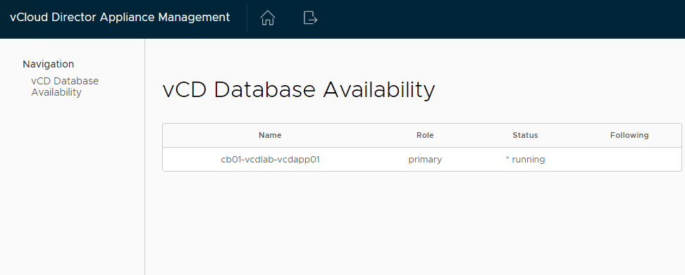
11 – On a successful deployment, log into the appliance 5480 page, and you should see something similar to:
12 – The primary appliance has successfully been deployed. If additional standby appliances are needed, now would be the best time to deploy them.
End – That’s it. In upcoming blog posts, I’ll walk through the process of deploying additional standby appliances, and the initial configuration of vCloud Director.
For the purposes of this demonstration, I will be configuring NFS services on a CentOS 7 VM, deployed to a vSphere 6.7 U3 homelab environment.
NFS Server VM Configuration
Host Name: cb01-nfs01 IP Address: 10.0.0.35 CPU: 2 RAM: 4GB
Disk 1: 20GB – Linux installation (thin provisioned) Disk 2: 100GB – Will be used for the vCD NFS share (thin provisioned)
Configure the vCD NFS share disk
For this demonstration, I have chosen not to configure Disk 2 that was added to the VM. Therefore, this “how-to” assumes that a new disk has been added to the VM, and the NFS server has been powered on after.
1) Open a secure shell to the NFS server. I have switched to the root account. 2) On my NFS server, the new disk will be “/dev/sdb”, if you are unsure run the following command to identify the new disk on yours:
fdisk -l
3) We need to format the newly added disk. In my case /dev/sdb. So run the following command:
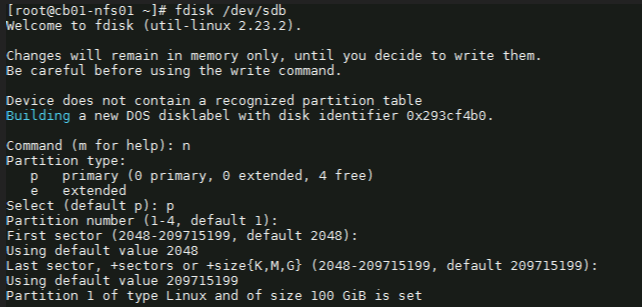
fdisk /dev/sdb
4) Next with the fdisk utility, we need to partition the drive. I used the following sequence: (for new partition) : n (for primary partition) : p (default 1) : enter (default first sector) : enter (default last sector) : enter
5) Before saving the partition, we need to change it to ‘Linux LVM’ from its current format ‘Linux’. We’ll first use the option ‘t’ to change the partition type, then use the hex code ‘8e’ to change it to Linux LVM like so:
Command (m for help): t Selected partition 1
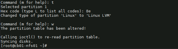
Hex code (type L to list all codes): 8e Changed type of partition ‘Linux’ to ‘Linux LVM’.
Command (m for help): w
Once you see “Command (m for help):” type ‘w’ to save the config.
Create a ‘Physical Volume, Volume Group and Logical Volume
6) Now that the partition is prepared on the new disk, we can go ahead and create the physical volume with the following command:
# pvcreate /dev/sdb1
7) Now we to create a volume group. You can name it whatever suites your naming standards. For this demonstration, I’ve created a volume group named vg_nfsshare_vcloud_director using /dev/sdb1, using the following command:
# vgcreate vg_nfsshare_vcloud_director /dev/sdb1
Creating a volume group allows us the possibility of adding other devices to expand storage capacity when needed.
8) When it comes to creating logical volumes (LV), the distribution of space must take into consideration both current and future needs. It is considered good practice to name each logical volume according to its intended use. – In this example I’ll create one LV named vol_nfsshare_vcloud_director using all the space. – The -n option is used to indicate a name for the LV, whereas -l (lowercase L) is used to indicate a percentage of the remaining space in the container VG. The full command used looks like: # lvcreate -n vol_nfsshare_vcloud_director -l 100%FREE vg_nfsshare_vcloud_director
9) Before a logical volume can be used, we need to create a filesystem on top of it. I’ve used ext4 since it allows us both to increase and reduce the size of the LV. The command used looks like:
Writing the filesystem will take some time to complete. Once successful you will be returned to the command prompt.
Mounting the Logical Volume on Boot
10) Next, create a mount point for the LV. This will be used later on for the NFS share. The command looks like:
# mkdir -p /nfsshare/vcloud_director
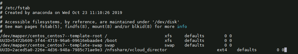
11) To better identify a logical volume we will need to find out what its UUID (a non-changing attribute that uniquely identifies a formatted storage device) is. The command looks like:
To see that it was successfully mounted, use the following command similar to:
# mount | grep nfsshare
Assign Permissions to the NFS Share
14) According to the Preparing the Transfer Server Storage section of the vCloud DIrector 10.0 guide, you must ensure that its permissions and ownership are 750 and root:root .
Setting the permissions on the NFS share would look similar to:
# chmod 750 /nfsshare/vcloud_director
Setting the ownership would look similar to:
# chown root:root /nfsshare/vcloud_director
Install the NFS Server Utilities
15) Install the below package for NFS server using the yum command:
# yum install -y nfs-utils
16) Once the packages are installed, enable and start NFS services:
# systemctl enable nfs-server rpcbind
# systemctl start nfs-server rpcbind
16) Modify /etc/exports file to make an entry for the directory /nfsshare/vcloud_director .
– According to the Preparing the Transfer Server Storage guide, the method for allowing read-write access to the shared location for two cells named vcd-cell1-IP and vcd-cell2-IP is the no_root_squash method.
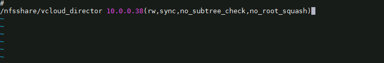
# vi /etc/exports
17) For this demonstration, my vCD appliance IP on the second nic is 10.0.0.38, so I add the following:
– There must be no space between each cell IP address and its immediate following left parenthesis in the export line. If the NFS server reboots while the cells are writing data to the shared location, the use of the sync option in the export configuration prevents data corruption in the shared location. The use of the no_subtree_check option in the export configuration improves reliability when a subdirectory of a file system is exported. – As this is only a lab, I only have a single vCD appliance for testing. If a proper production deployment, add additional lines for each appliance IP.
18) Each server in the vCloud Director server group must be allowed to mount the NFS share by inspecting the export list for the NFS export. You export the mount by running exportfs -a to export all NFS shares. To re-export use exportfs -r.
# exportfs -a
– To check the export, run the following command:
# exportfs -v
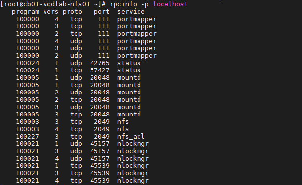
– Validate NFS daemons are running on the server by using rpcinfo -p localhost or service nfs status. NFS daemons must be running on the server.
# rpcinfo -p localhost
or
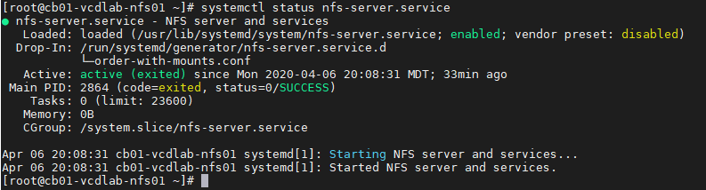
# systemctl status nfs-server.service
Configure the Firewall
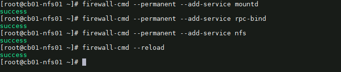
19) We need to configure the firewall on the NFS server to allow NFS client to access the NFS share. To do that, run the following commands on the NFS server. # firewall-cmd --permanent --add-service mountd # firewall-cmd --permanent --add-service rpc-bind # firewall-cmd --permanent --add-service nfs # firewall-cmd --reload
20) That’s it. Now we can deploy the vCloud Director 10.0 appliance(s).
Optional NFS Share Testing
I highly recommend testing the NFS share before continuing with the vCloud DIrector 10.0 appliance deployment. For my testing, I have deployed a temporary CentOS 7 VM, with the same hostname and IP address as my first vCD appliance. I have installed nfs-utils on my test VM. # yum install -y nfs-utils
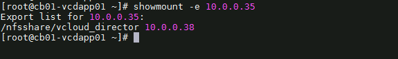
OT-1) Check the NFS shares available on the NFS server by running the following command on the test VM. change the IP and share here to your NFS server.
# showmount -e 10.0.0.35
As you can see, my mount on my NFS server is showing one exported list for 10.0.0.38, my only vCD appliance
OT-2) Create a directory on NFS test VM to mount the NFS share /nfsshare/vcloud_director which we have created on the NFS server. # mkdir -p /mnt/nfsshare/vcloud_director
OT-3) Use below command to mount the NFS share /nfsshare/vcloud_director from NFS server 10.0.0.35 in /mnt/nfsshare/vcloud_director on NFS test VM.
# mount 10.0.0.35:/nfsshare/vcloud_director /mnt/nfsshare/vcloud_director
OT-4) Verify the mounted share on the NFS test VM using mount command.
# mount | grep nfsshare
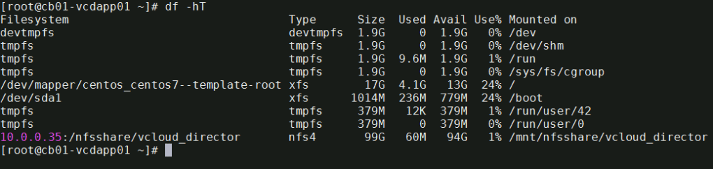
You can also use the df -hT command to check the mounted NFS share.
# df -hT
OT-5) Next we’ll create a file on the mounted directory to verify the read and write access on NFS share. IMPORTANT** during the vCD appliance deployment, it is expected that this directory is empty, else it could make the deployment fail. Remember to cleanup after the test.
# touch /mnt/nfsshare/vcloud_director/test
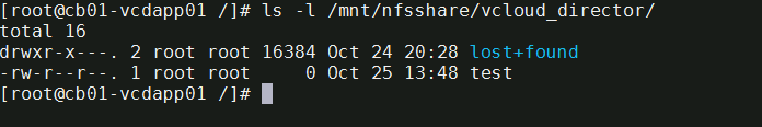
OT-6) Verify the test file exists by using the following command:
# ls -l /mnt/nfsshare/vcloud_director/
OT-7) Clean your room. Cleanup the directory so that it is ready for the vCD deployment.
# rm /mnt/nfsshare/vcloud_director/test
After successfully testing the share, we now know that we can write to that directory from the vCD appliance IP address, and that we can remove files.
In my next post, I will cover deploying the vCloud Director 10.0 appliance. Stay tuned!
I realize that writing up this blog post now, may be irrelevant considering most if not all VMware customers are well beyond NSX appliance 6.2.4. But some folks may still find the information shared here still relevant. At the very least the instructions for restarting the bluelane-manager service on the NSX appliance is still something handy to keep in your Rolodex of commands.
There’s an interesting bug in versions of the NSX appliance ranging from versions 6.2.4 – 6.2.8, where the utilization slowly climbs, eventually maxing out at 100% CPU utilization after few hours. For my environment, we had vSphere version 6, and roughly 60 hosts that were also on ESXi 6. We were also using traditional SAN storage on FCOE. In this case a combination of IBM XIV, and INFINIDATs. In most cases, we could just restart the NSX appliance, which would resolve the CPU utilization issue, however sometimes within two hours, the CPU utilization would climb back up to 100% again. When the appliance CPU maxed out, after a few seconds the NSX manager user interface would typically crash.
“This issue occurs when the PurgeTask process is not purging the proper amount of job tasks in the NSX database causing job entries to accumulate. When the number of job entries increase, the PurgeTask process attempts to purge these job entries resulting in higher CPU utilization which triggers (GC) Garbage Collection. The GC adds more CPU utilization.”
The only problem with the KB, is that our environment was currently on 6.2.4, so clearly the problem was not resolved.
In order to buy ourselves some time, without needing to restart the NSX appliance, we found that simply restarting a service on the NSX appliance called ‘bluelane-manger‘, had the same affect, but this was only a work around.
You can take the following steps to restart the bluelane-manager service:
SSH to the NSX Manager using the ‘admin’ account
Type
en
Type:
st en
When prompted for the password, type:
IAmOnThePhoneWithTechSupport
To get the status of the bluelane manager service type:
/etc/rc.d/init.d/bluelane-manager status
To restart the bluelane-manager service, type:
/etc/rc.d/init.d/bluelane-manager restart
Now after a few seconds, you should notice that the NSX appliance user interface has restored to normal functionality, and you can log in, and validate that the CPU has fallen to normal usage.
What made the issue worse, was the fact that we had hosts going into the purple diagnostic screen. I’m not talking one or two here. Imagine having over 20 ESXi hosts drop at the same time, during production hours, and keep in mind that all of these hosts were running customer workloads….. If you’ll excuse the vulgarity, that certainly has a pucker factor exceeding 10. At the time, I was working for a service provider running vCloud Director. The customers were basically sharing the ESXi host resources. We were also utilizing VMware’s Guest Introspection (GI) service, as we also had trend micro deployed, and as a result most customers were sitting in the default security group.
Through extensive troubleshooting with VMware developers, at a high level we determined the following: Having all customer VMs in the default NSX security group, every time a customer VM powered on or off, was created or destroyed, vMotioned, replicated in or out of the environment, all had to be synced back to the NSX appliance, which then synced with the ESXi hosts. Looking at the at specific logs on the ESXi hosts that only VMware had access to, we saw a backlog of sync instructions that the hosts would never have time to process, which was contributing to the NSX appliance CPU issue. This was also causing the hosts to eventually purple screen. Fun fact was that by restarting the hosts we could buy ourselves close to two weeks before the issue would reoccur, however, performing many simultaneous vMotions would also cause 100% CPU on the NSX appliance, which would put us into a bad state again.
Thankfully, VMware was currently working on a bug fix release at the time NSX 6.2.8, and our issue served to spur the development team along in finalizing the release, along with adding a few more bug fixes they had originally thought was resolved in the 6.2.4 release.
Most relevant to our issues that we faced were the following fixes:
Fixed Issue 1849037: NSX Manager API threads get exhausted when communication link with NSX Edge is broken
Fixed Issue 1704940: You may encounter the purple diagnostic screen on the ESXi host if the pCPU count exceeds 256
Fixed Issue 1760940: NSX Manager High CPU triggered by many simultaneous vMotion tasks
Fixed Issue 1813363: Multiple IP addresses on same vNIC causes delays in firewall publish operation
Fixed Issue 1798537: DFW controller process on ESXi (vsfwd) may run out of memory
Upgrading to NSX 6.2.8 release, and rethinking our security groups, brought stability back to our environment, although not all above issues were completely resolved as we later found out. In short most “fixes” were really just process improvements under the hood. Specifically we could still cause 100% CPU utilization on the NSX appliance by putting too many hosts into maintenance mode consecutively, however at the very least the CPU utilization was more likely able to recover on its own, without us needed to restart the service or appliance. Now why is that important you might ask? Being a service provider, you want to quickly and efficiently roll through your hosts while doing upgrades, and having something like this inefficiency in the NSX code base, can drastically extend maintenance windows. Unfortunately for us at the time, as VMware came out with the 6.2.8 maintenance patch after 6.3.x, so the fixes were also not apart of the 6.3.x release yet. KB2150668
As stated above, the instructions for restarting the bluelane-manager service on the NSX appliance is still something that is very handy to have.
VMware’s vCloud Director (vCD) and vCloud Availability (vCAV) only come with TLS v1.1 and 1.2 enabled out of the box. This process will show you how to enable TLS v1. If more information is needed, please visit VMware’s Documentation on vCloud Director 8.20, or the following KB2145796. This work should be completed after hours as you would inevitably be moving VCD proxy service from one cell to another, and this could cause a brief outage for customers. This process will require taking the cell offline, so do each cell one at a time starting with a cell not running the inventory service
Open an SSH session to a VCD cell, or vCAv cloud proxy cell, and su to root
Change to the ‘ /opt/vmware/vcloud-director/bin/ ‘ directory
Use the Cell Management Tool to quiesce the cell. This will move active jobs over to another cell, and cleanly shutdown the cell. You should make note which VCD cell has the proxy service enabled, and avoid that cell until last.
You just need to generate the java heap dump from one of the cells. What you’ll need to succeed:
JCONSOLE
IP tables disabled on the cell you are connecting to.
Disk space available on the cell to accommodate the dump – I believe these can be between 8 and 10 GB in size
Unless an emergency, do this operation outside of normal business hours as it will be CPU intensive for up to 3 minutes, can impact API call performance, and can potentially cause the VCD cell inventory service to hang.
Step #1: Disable iptables on the cell
ssh to the desired cell and run the following command:
# service iptables stop
Step #2: Connect with jconsole (java console)
domain credentials should work here depending on your environment
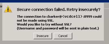
connect to port: 8999
connect to desired cell
If you get this message “Secure connection failed. Retry Insecurely?” just click the ‘insecure’ button to continue
Step #3: Generate the heap dump
On the MBeans tab, in the com.sun.management/HotSpotDiagnostics object, select the Operation section.
In dumpHeap parameters, enter the following information:
p0: [heap-output-path]
p1: true – do a garbage collection before dump heap
There will be no indication that the heapdump completes. I just watch the size of the file until the growth stops on the cell. This process typically takes less than two minutes.
Step #4: Cleanup and send-off
Locate the heap dump in /opt/vmware/vcloud-director/ and move off to a location where you can compress and upload to VMware FTP site as you would for logs.
Start the iptables on the cell: # service iptables start
This document was creating while upgrading an existing vCloud Director 8.10.1 environment with an Oracle database, and multiple cloud cells.
After downloading the latest version of vCloud Director 8.20 for service providers, SCP the upgrade to all VCD cells. You can review the release notes here.
I strongly advise opening an support request with VMWare before proceeding with the upgrade. You may not need it, but it comes in handy having one logged beforehand.
Maintenance – Shutdown the cells
1. Open an SSH session into each VCD cell
2. Sudo to root using the following command:
# sudo su -
3. Change to the vcloud-director/bin/ directory
# cd /opt/vmware/vcloud-director/bin/
4. Use the Cell Management Tool to quiesce the cell. This will move active jobs over to another cell.
7. Get a status on the cells to be sure everything is down
# service vmware-vcd status
8. Now complete steps 4 – 7 on the remaining cells to cleanly shutdown the vCD service on all cells.
9. Here is where I would shutdown the VCD cell virtual machines, and database to get a clean snapshot while the environment is powered off
10. Once the database virtual machine is fully up, power-on the VCD cell virtual machines.
11. Log back into the vCloud Director environment to verify functionality before the upgrade.
12. SSH to all VCD cell virtual machines and use the following command to stop the service again on each cell. Here there is an assumption made that we are now well within a maintenance window.
# service vmware-vcd stop
Starting The vCloud Director Upgrade
1. Start with the first cell, and run the first half of the upgrade. DO NOT upgrade the database yet.
3. Stop. Now you need to run steps one and two on the rest of the vCloud Director Cells, and install the upgrade. Do them one at a time. DO NOT upgrade the database yet.
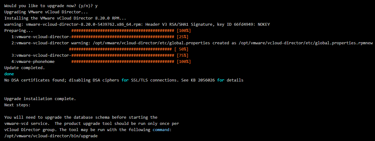
4. Now that all cells have been upgraded, go back to the first cell and run the database upgrade.
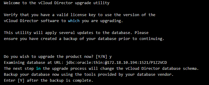
# ./opt/vmware/vcloud-director/bin/upgrade
Example vCD Database upgrade output:
5. Respond with: y
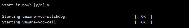
6. Start the the first cell by responding with ‘y’
7. Manually start the VCD service on the remaining cells
# service vmware-vcd start
8. Get the VCD status of all cells by running the following command on each
# service vmware-vcd status
9. Log into the cell, and watch/wait for vCenter to sync with vCD under the Manage & Monitor section → vCenters. This normally takes 30 minutes or so. Once done the status will change from a spinning circle to a green check mark.
10. Run some environment validation tests to be sure everything is working and is proper, and then delete those snapshots taken earlier.
We use NSX to serve up the edges in vCloud Director environment currently running on 8.10.1. One of the important caveats to note here, that when you do upgrade an NSX 6.2.4 appliance in this configuration, you will no longer be able to redeploy the edges in vCD until you upgrade and redeploy the edge first in NSX. Then and only then will the subsequent redeploys in vCD work. The cool thing about that though, is VMware finally has a decent error message that displays in vCD if you do try to redeploy an edge before upgrading it in NSX, you’d see an error message similar to:
—————————————————————————————————————–
“[ 5109dc83-4e64-4c1b-940b-35888affeb23] Cannot redeploy edge gateway (urn:uuid:abd0ae80) com.vmware.vcloud.fabric.nsm.error.VsmException: VSM response error (10220): Appliance has to be upgraded before performing any configuration change.”
—————————————————————————————————————–
Now we get to the fun part – The Upgrade…
A little prep work goes a long way:
If you have a support contract with VMware, I HIGHLYRECOMMEND opening a support request with VMware, and detail with GSS your upgrade plans, along with the date of the upgrade. This allows VMware to have a resource available in case the upgrade goes sideways.
Make a clone of the appliance in case you need to revert (keep powered off)
Set host clusters DRS where vCloud Director environment/cloud VMs are to manual (keeps VMs/edges stationed in place during upgrade)
Disable HA
Do a manual backup of NSX manager in the appliance UI
Shutdown the vCloud Director Cell service
It is highly advisable to stop the vcd service on each of the cells in order to prevent clients in vCloud Director from making changes during the scheduled outage/maintenance. SSH to each vcd cell and run the following in each console session:
# service vmware-vcd stop
A good rule of thumb is to now check the status of each cell to make sure the service has been disabled. Run this command in each cell console session:
# service vmware-vcd status
For more information on these commands, please visit the following VMware KB article: KB1026310
Upgrading the NSX appliance to 6.2.8
Log into NSX manager and the vCenter client
Navigate to Manage→ Upgrade
Click ‘upgrade’ button
Click the ‘Choose File’ button
Browse to upgrade bundle and click open
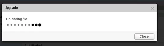
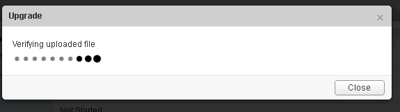
Click the ‘continue button’, the install bundle will be uploaded and installed.
You will be prompted if you would like to enable SSH and join the customer improvement program
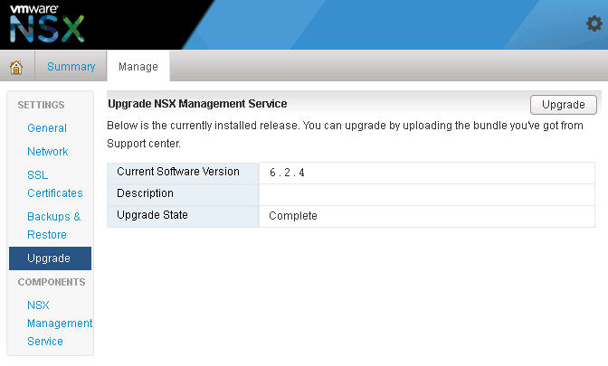
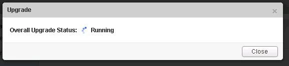
Verify the upgrade version, and click the upgrade button.
The upgrade process will automatically reboot the NSX manager vm in the background. Having the console up will show this. Don’t trust the ‘uptime’ displayed in the vCenter for the VM.
Once the reboot has completed the GUI will come up quick but it will take a while for the NSX management services to change to the running state. Give the appliance 10 minutes or so to come back up, and take the time now to verify the NSX version. If using guest introspection, you should wait until the red flags/alerts clear on the hosts before proceeding.
In the vSphere web client, make sure you see ‘Networking & Security’ on the left side. If it does not show up, you may need to ssh into the vCenter appliance and restart the web service. Otherwise continue to step 12.
# service vsphere-client restart
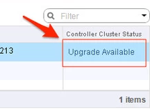
12. In the vsphere web client, go to Networking and Security -> Installation and select the Management Tab. You have the option to select your controllers and download a controller snapshot. Otherwise click the “Upgrade Available” link.
13. Click ‘Yes’ to upgrade the controllers. Sit back and relax. This part can take up to 30 minutes. You can click the page refresh in order to monitor progress of the upgrades on each controller.
14. Once the upgrade of the controllers has completed, ssh into each controller and run the following in the console to verify it indeed has connection back to the appliance
# show control-cluster status
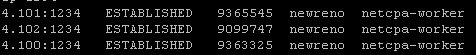
15. On the ESXi hosts/blades in each chassis, I would run this command just as a sanity check to spot any NSX controller connection issues.
esxcli network ip connection list | grep 1234
If all controllers are connected you should see something similar in your output
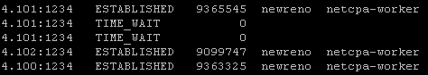
If controllers are not in a healthy state, you may get something similar to this next image in your output. If this is the case, you can first try to reboot the controller. If that doesn’t work try a reboot. If that doesn’t work…..weep in silence. Then call VMware using the SR I strongly suggested creating before the upgrade, and GSS or your TAM can get you squared away.
16. Now in the vSphere web client, if you go back to Network & Security -> Installation -> Host Preparation, you will see that there in an upgrade available for the clusters. Depending on the size of your environment, you may choose to do the upgrade now or at a later time outside of the planned outage. Either way you would click on the target cluster ‘Upgrade Available’ link and select yes. Reboot one host at a time that way the vibs are installed in a controlled fashion. If you simply click resolve, the host will attempt to go into maintenance mode and reboot.
17. After the new vibs have been installed on each host, run the following command to be sure they have the new vib version:
# esxcli software vib list | grep -E 'esx-dvfiler|vsip|vxlan'
Start the vCloud Director Cell service
On each cell run the following commands
To start:
# service vmware-vcd start
Check the status after :
# service vmware-vcd status
Log into VCD and by now the inventory service should be syncing with the underlining vCenter. I would advise waiting for it to complete, then run some sanity checks (provision orgs, edges, upgrade edges, etc)


You must be logged in to post a comment.