In my previous bog HERE, I walk through the steps of creating a backup directory on a QNAP NAS, enable SFTP connections, and created a service account. In this blog, I will complete the backup configuration in the SDDC manager for this VCF 9 deployment in my home lab.
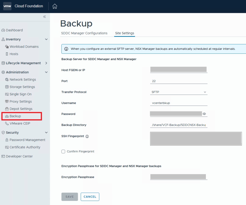
For VCF 9.0.X, and previous versions, you log into the SDDC manager, and click on Backup on the left side menu under Administration. On the “Site Settings” tab, you then fill in your specifics for backup configuration.
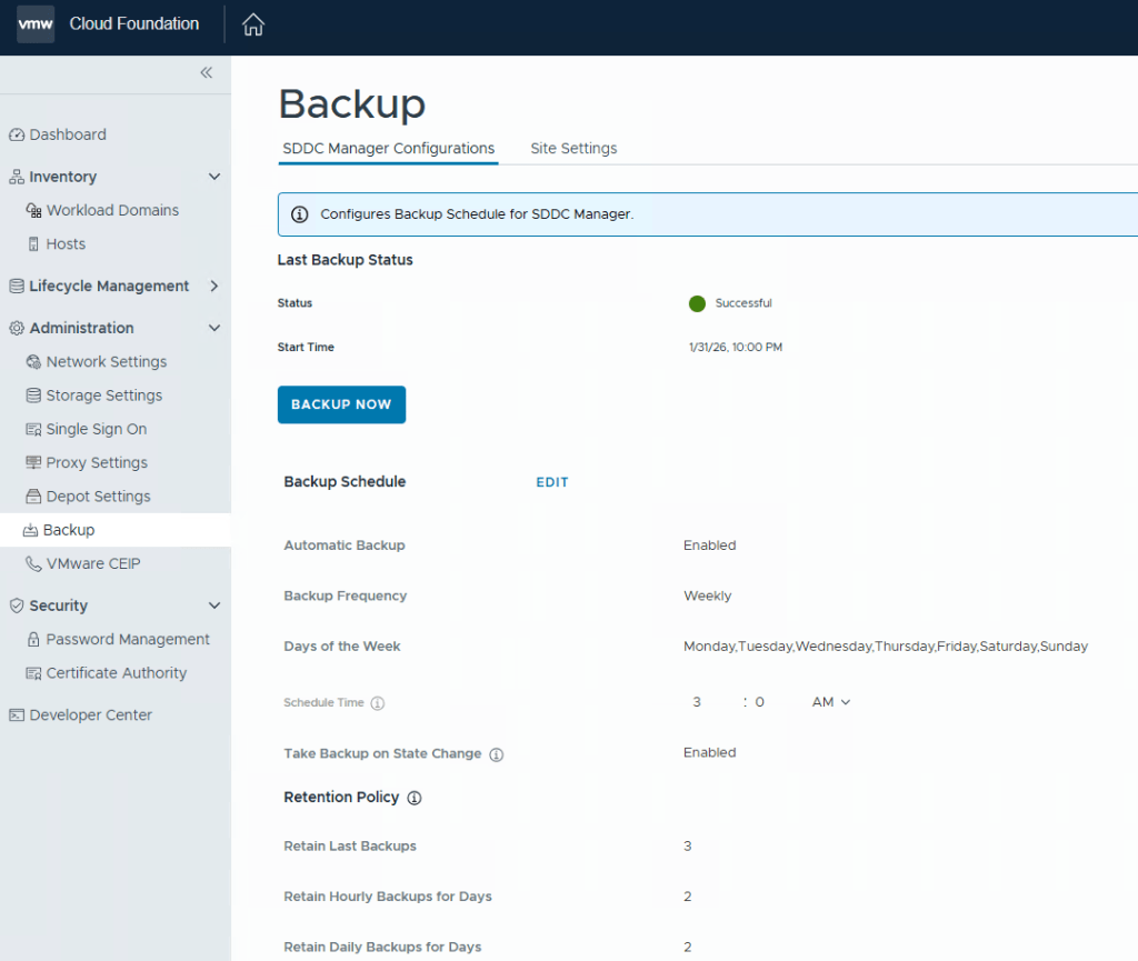
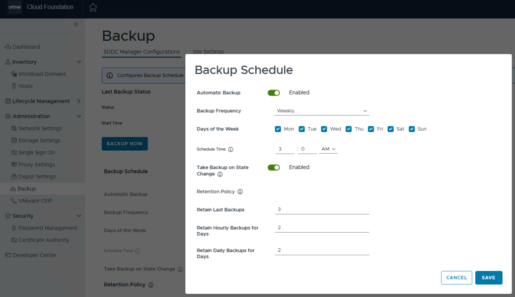
After you click the Save button, go back to the “SDDC Manager Configurations” tab, and now you will be able to click “EDIT” next to the backup schedule.
You can define the backup schedule to suit your needs depending on how busy your environment is, and how often workload domains are updated. This schedule however, does not reflect your NSX backup which is counter intuitive considering enabling the backups in the SDDC manager also enables the backups in NSX. Just not the schedule.
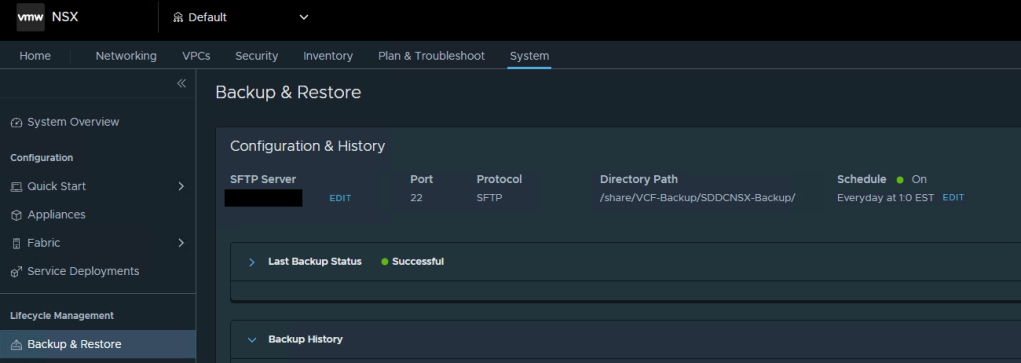
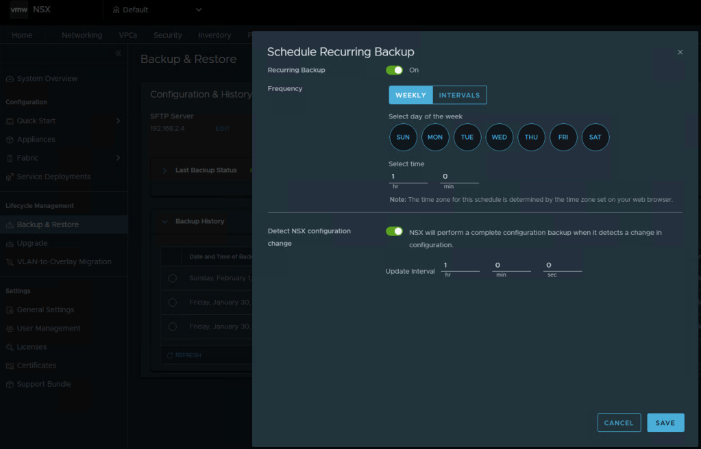
To modify the NSX backup schedule, you’ll need to log into NSX, click the “System” tab, and then select “Backup & Restore” under Lifecycle management on the left menu.
Here you can click “EDIT” to adjust the NSX backup schedule to suite your needs. Click SAVE when finished.
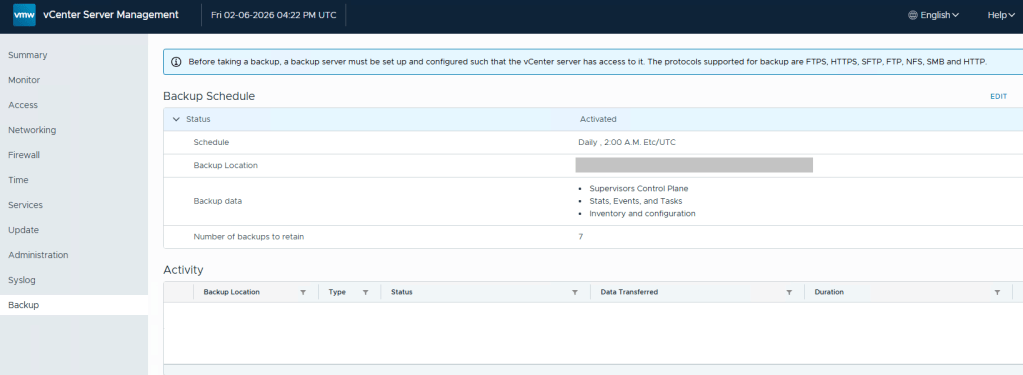
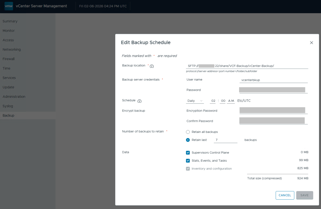
Lastly, we still need to define the backups schedule in the vCenter 5480/vami administration page.
Define the backup schedule that will suit the needs for your environment. Keep in mind that when you install updates/upgrades to the VCF environment, the pre-check will fail if there’s not a recent backup within the last 24 hours. My advise here would be to schedule daily backups to avoid the precheck critical failure. Honestly, it should just be a warning, but I digress…
After you define a backup schedule, it’s a good idea to manually kick off a backup job to be sure the configuration works.
Continuing my series on my new VCF 9 Home Lab build (My VMware Cloud Foundation 9 Home Lab), in this post I’ll go over the basic setup for SFTP backups that need to be configured for the SDDC, NSXT, and vCenter, using my QNAP NAS.
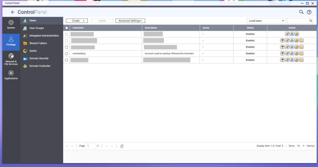
First, a service account should be created for these backup jobs. In this example, I have a service account called ‘vcenterbkup’ already created for my old VMware lab, and just plan to reuse it. You can either make this user part of the administrators group to allow SSH/SFTP connections, or you can tinker and edit the SSH configuration files (e.g., /etc/config/ssh/sshd_config) by adding AllowUsers directives.
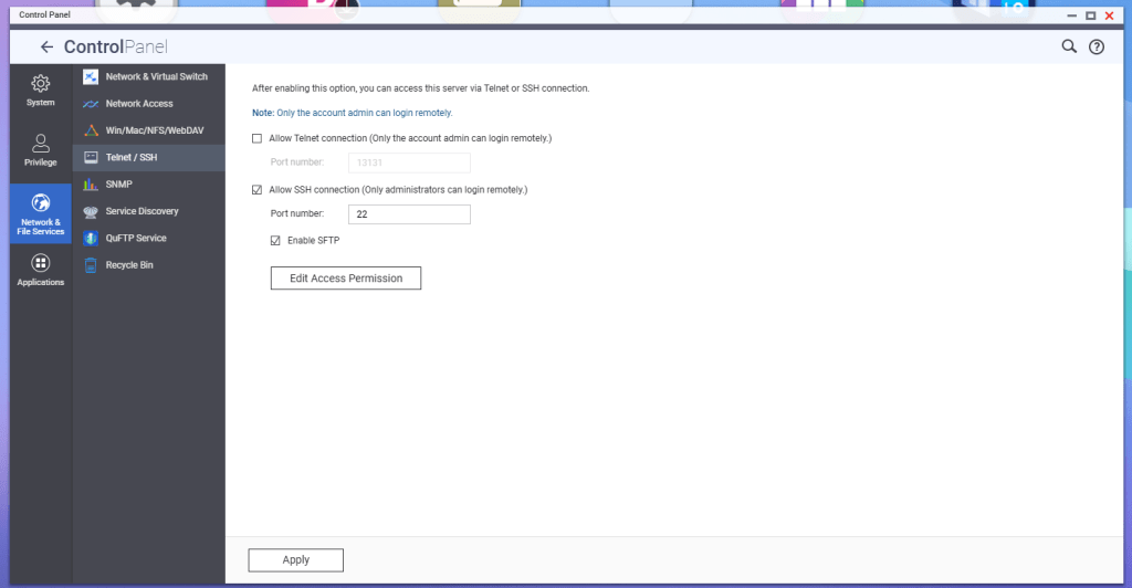
According to QNAP, in order to enable SFTP connections to the NAS, the SSH service must be enabled first, and then the SFTP enablement will be available. Go to Telnet/SSH in the Control Panel, and enable these services.
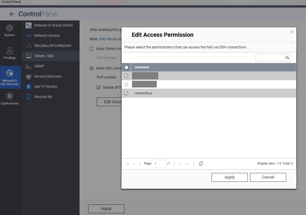
Hit the Edit Access Permission button, and add the service account created earlier, in this example ‘vcenterbkup’.
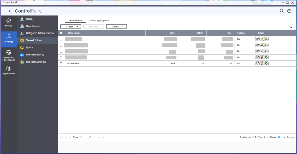
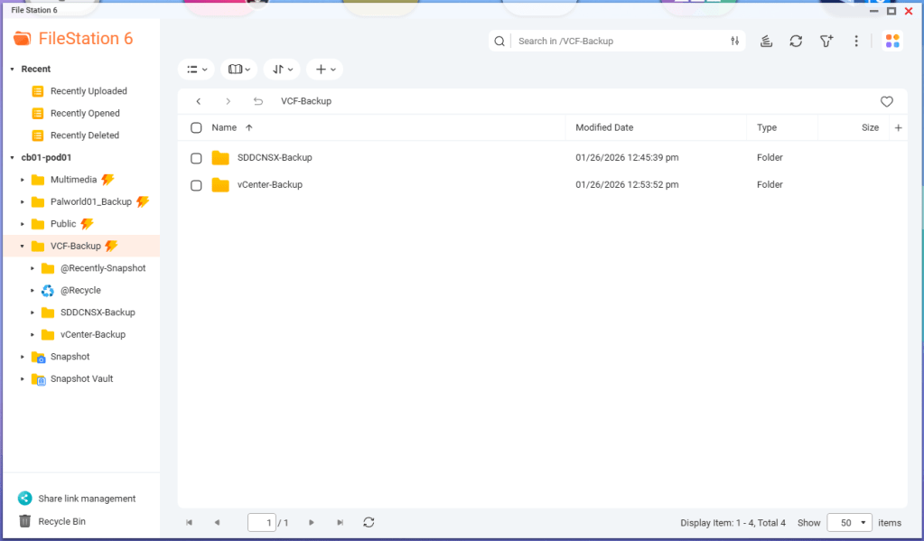
You’ll need to create a shared folder on the NAS, and assign the service account created earlier, in this example ‘vcenterbkup’, with read/write privileges. In this example, I used the folder name of ‘VCF-Backup’.
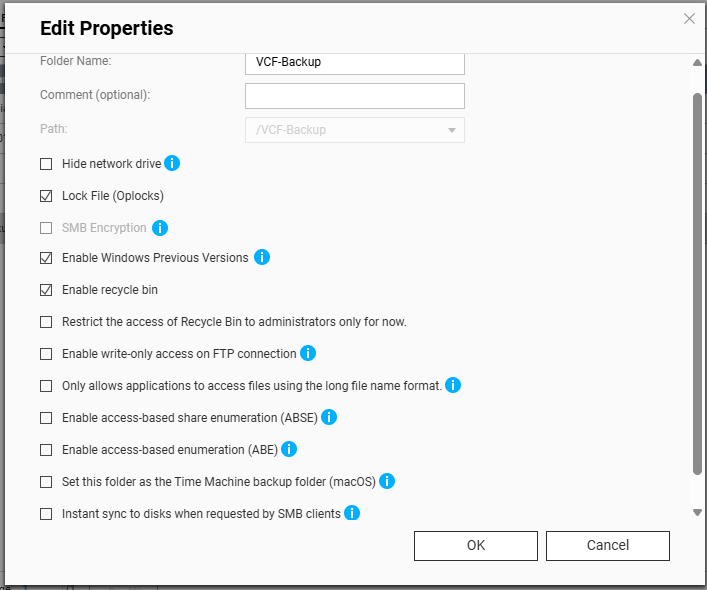
The size of the folder will depend on your backup strategy for your home lab. One important note, even though the folder path shows as “/VCF-Backup” in the UI, the actual directory will be ‘/share/VCF-Backup/ ‘. This will be important later when backups in the SDDC manager and vCenter are configured.
Lastly, I created sub directories inside the VCF-Backup folder. One called ‘SDDCNSX-Backup’, and the other called ‘vCenter-Backup’.
In my next blog, I’ll cover configuring the backups in the SDDC manager, NSXT, and vCenter. NSXT gets configured when the backups are configured in the SDDC manager, however it will need to be tweaked.
If you’ve been following along in this home lab series, in my previous blog, I finished my VCF 9.0.1 deployment to my 4 MINIS FORUM MS-A2s HERE.
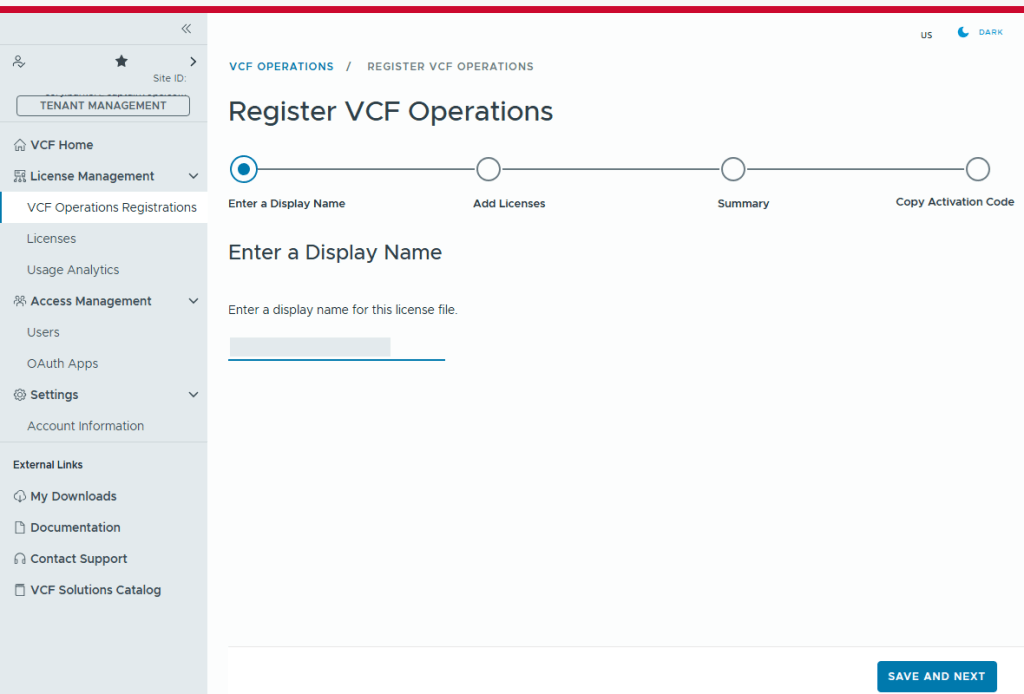
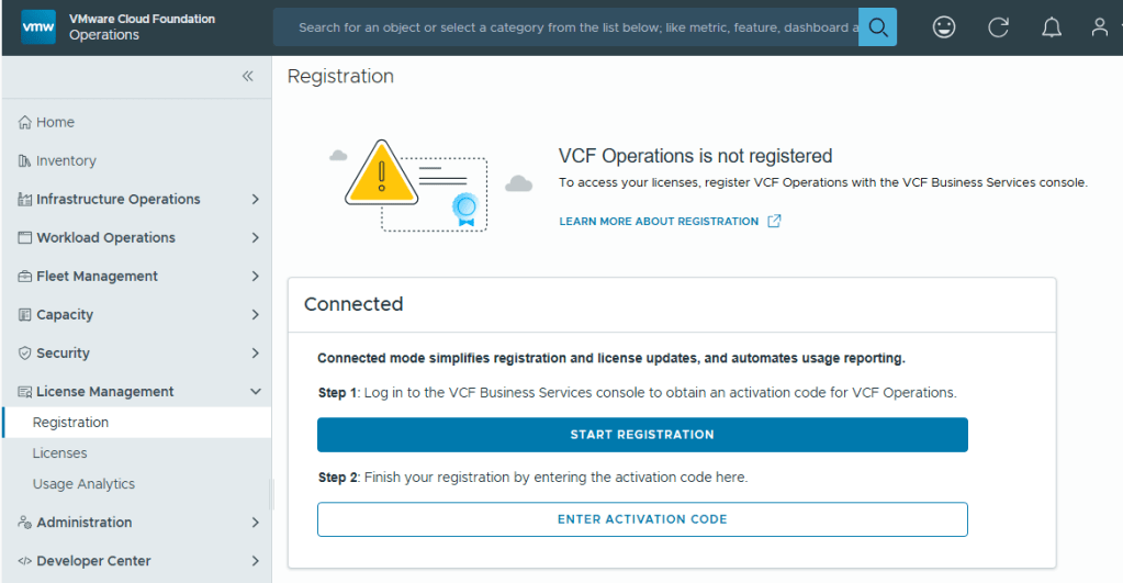
With Broadcom’s VCF 9, we are now required to configure usage reporting. This process is pretty straight forward. Click on the [START REGISTRATION] button, and you’ll be redirected to the Broadcom portal for authentication.
You’ll need to enter a display name for this license file. It could be representative of the environment where used.
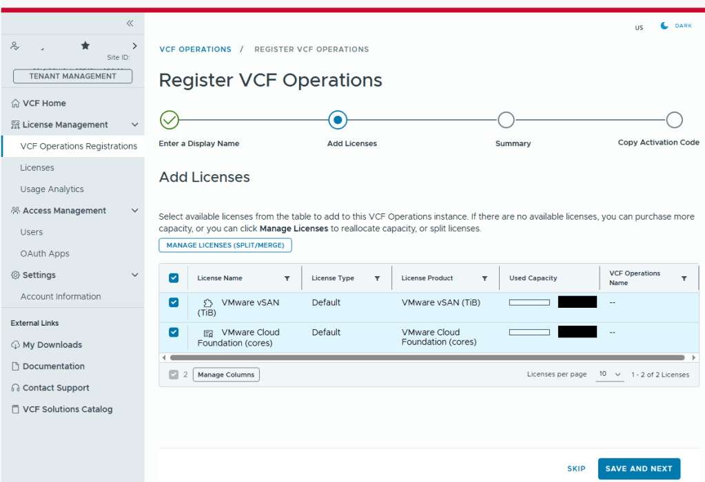
Select the licenses needed for the environment..
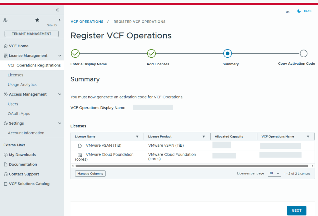
Validate the selection.
Now we just need to copy the activation code.
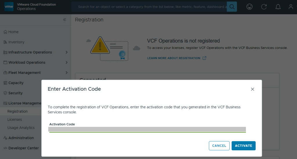
Back in VCF Operations, we now click the [ENTER ACTIVATION CODE] button to paste in the code.
With your Activation Code ready, now you can activate.
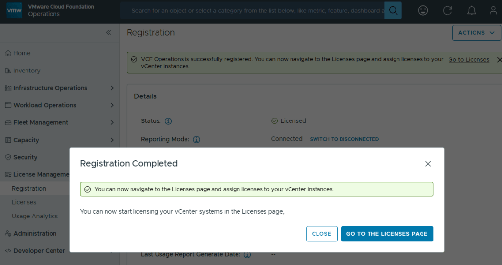
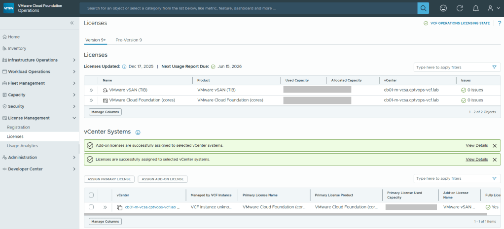
Now your licenses will be available to apply to vCenter (PRIMARY LICENSE) and vSAN (ADD-ON LICENSE).
But wait… There’s More!
I am rather surprised that we have to apply the download token twice considering it’s a requirement to download the bits for the installation, especially in a world where we are constantly striving to automate all the things. Maybe Broadcom’s VCF Engineering division just overlooked this simple quality of life automation task to copy said download Token from the Cloud Installer, and import it to VCF Operations?
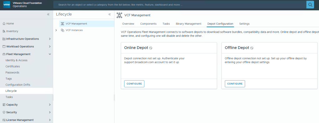
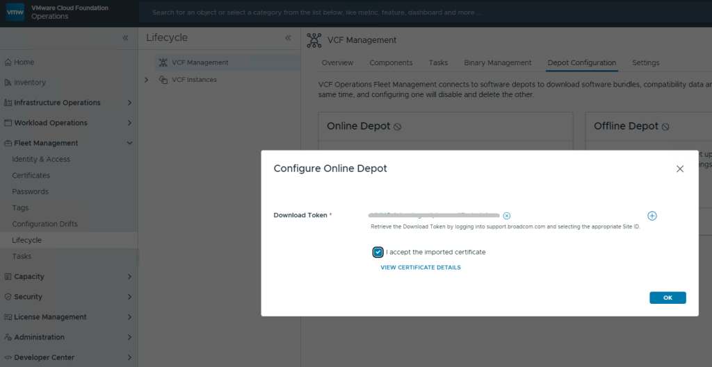
You’ll want to add your download token again to VCF Operations: Fleet Management ->Lifecycle ->Depot Configuration
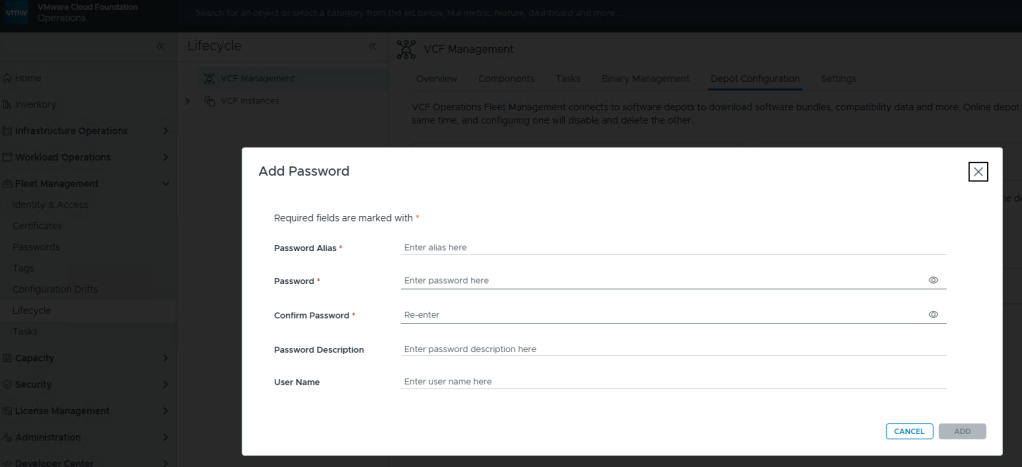
This looks oddly familiar for creating a credential file for VCF (Aria) Operations Integration. Click the plus icon.
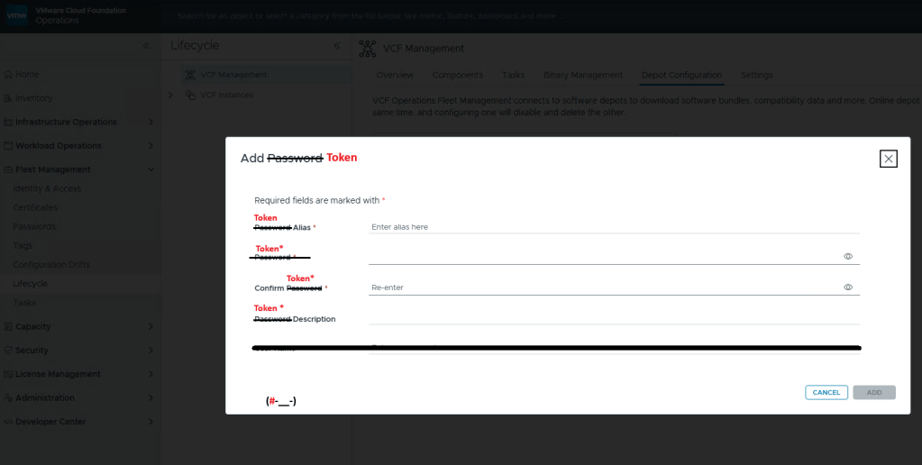
Well that’s… disappointing.
I fixed it for you, Broadcom.
Just like you would create a credential file, here you add your download token where you’d add your password, and click [ADD].
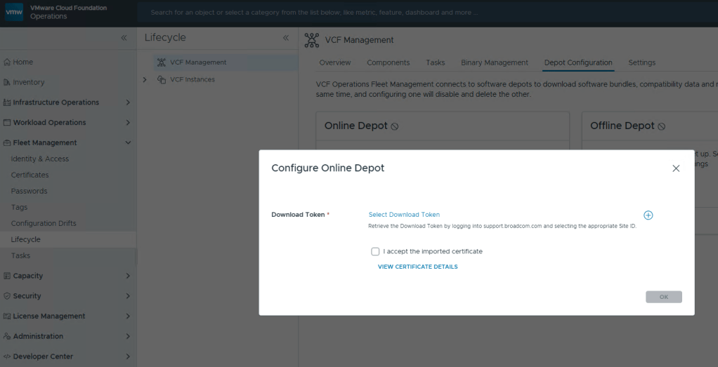
Now just select your Download Token and click [OK].
In this blog, I’ll go over the basic deployment of the VMware Cloud Foundation Installer appliance (formally VCF Cloud Builder) OVA, because there’s a new ‘feature’ that will trip you up if you’re not careful.
We’ve all installed OVAs before, but for the Cloud Foundation Installer OVA, there was something that I wanted to call out.
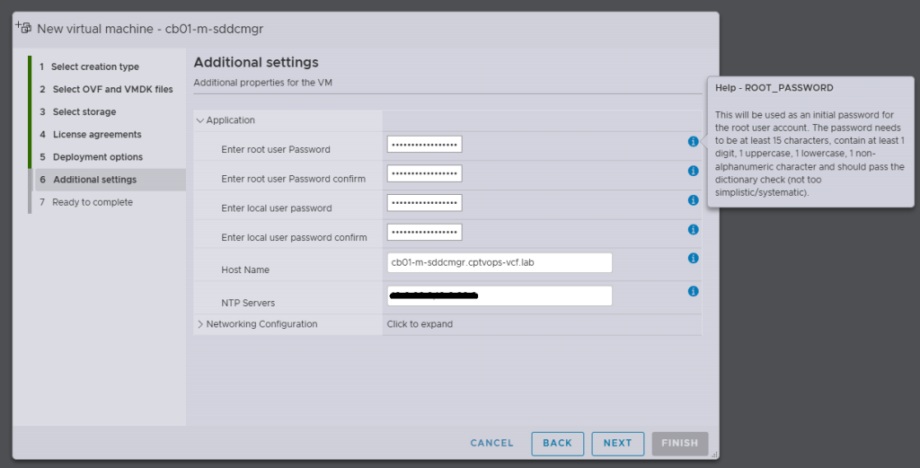
Specifically, when you’re deploying the OVA, be mindful of the new password requirements as they have changed. Previous versions of VCF through VCF 5.x, did not require a 15 character password. Apparently the quality control folks over in the VCF Division at Broadcom also forgot about this, because you can enter an 8 character passwords here, and the OVA deployment will continue as normal.
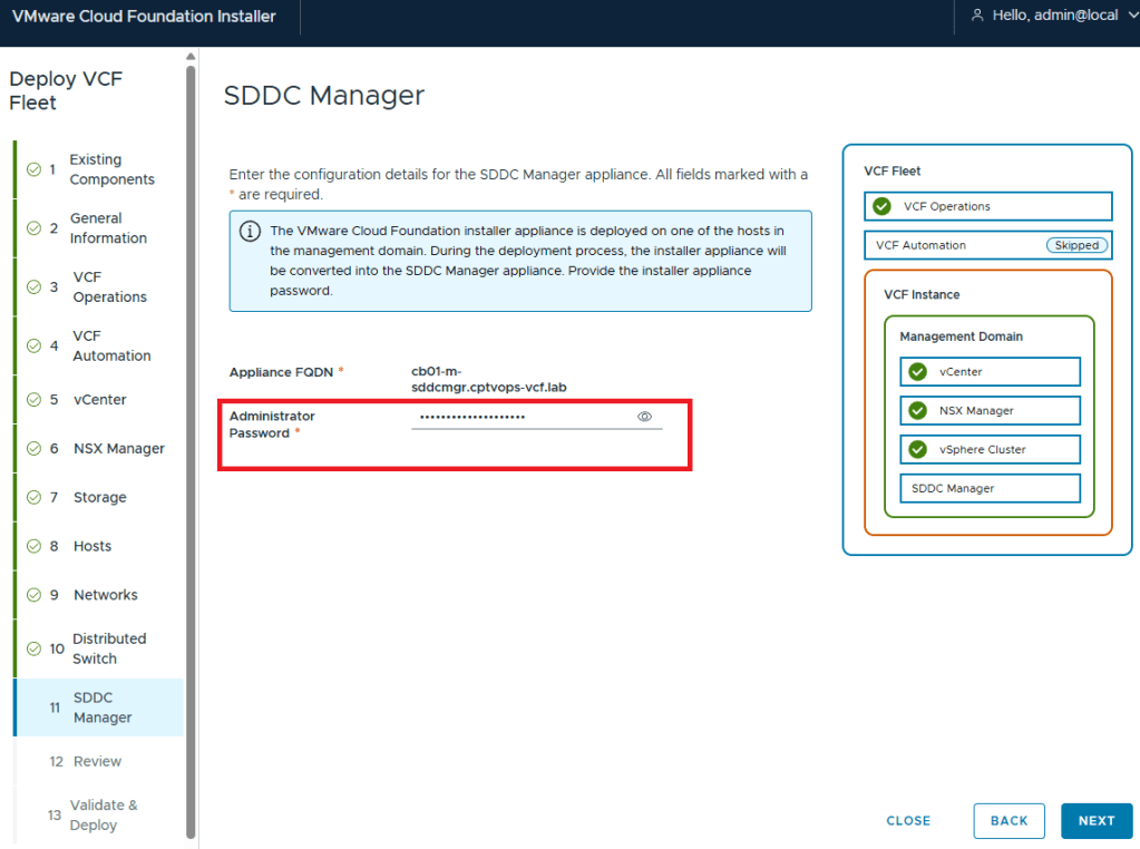
Why does this matter, well if we fast forward here a little bit, and get to where we are in the VMware Cloud Foundation deployment wizard on Step 11, you are again asked for the Administrator Password (local user). If you did not use at least a 15 character password during the OVA deployment, the wizard when you click [NEXT] will state that the Administrator password is incorrect . It doesn’t warn you that it is too short. So after a couple of tries, you will get kicked out of the wizard and back to the Cloud Foundation Installer login page, unable to log in because the local user (admin account) is now locked… I first observed this behavior during a customer deployment of 9.0, and found that the ‘feature’ is still there in the 9.0.1 I deployed for my home lab.
In this blog, I am going to share a problem I came across on a Professional Services engagement with a customer’s VMware Cloud Foundation 4.x environment, and our inability to remediate the root account of the NSX-T appliances.
Passwords had expired in the environment and showed disconnected in the SDDC manager UI. For the root, admin, and audit accounts, we were able to follow the following knowledge base article and get these accounts active on the NSX-T appliances: Credential operations fail on NSX Components in SDDC Manager. We tested these accounts and everything was working as expected on the appliances.
In the SDDC manager UI, we then were able to remediate and rotate the admin account for NSX-T appliances. However, while trying to remediate the root account with the known password that was already in the SDDC database, the operation failed. So we tried to create a brand new password for the root account on the NSX-T appliances, and then tried the to remediate the account again in the SDDC UI, but received the same error. “Failed to test: SSH credentials throughout the NSX-T cluster.”
Using the Reference Token from the failed task, I established an SSH connection to the SDDC appliance to review the operationsmanager log.
less /var/log/vmware/vcf/operationsmanager/operationsmanager.log
I then searched for the reference token “/OJB1CJ”, and found that the same error message given in the SDDC UI was given in the operationsmanager log. I was also finding javax.net.ssl.SSLHandshakeException error messages. I backed out of the log, and then validated that I could indeed SSH from the SDDC appliance to each of the NSX-T appliances, and that I could SSH from each of the NSX-T appliances back to the SDDC appliance, and validated that I could establish an SSH connection between each of the NSX-T appliances. Logging into the NSX-T UI, everything appeared to be happy and healthy. Lastly, I decided to check the self-signed certificates on each of the NSX-T appliances. NSX01 and NSX02 both looked proper, and had the correct FQDN for each, however, NSX03 appliance did not. Somehow it had the FQDN of the vip.
Suspecting it was the certificate on NSX03 that was hosing us, we used the VMware documentation to Replace Certificates of the NSX-T appliances with a signed certificate. We could NOT use the SDDC manager to replace the NSX-T certificates, because SDDC manager requires a good root account in order to use this automated function, and we could not fix the root account without having a proper certificates on the NSX-T appliances. We used one signed certificate across the three appliances and vip, and made sure the vip, NSX01, NSX02, and NSX03 were all in the SAN. We then validated that each NSX-T appliance had a healthy signed certificate with the padlock in the URL.
I went back to the SDDC manager UI, and was then able to successfully remediate the NSX-T root account for the workload domain. As previously mentioned above, we used Credential operations fail on NSX Components in SDDC Manager to set the accounts on the NSX-T cluster to match what the SDDC manager had, which is why we chose the password remediation option on the SDDC manager here. Now that we have validated that we have good NSX-T accounts in the SDDC manager, we now rotate the NSX-T cluster credentials so that new passwords will be generated.
In VMware Cloud Foundation 4.5.1, managing certificates of the Aria Suite LCM, NSX, VXRAIL, and vCenter Certificates should be done via the SDDC manager, so that it trusts the components certificate. The official documentation on how to do it can be found here -> Manage Certificates in a VMware Cloud Foundation.
In some cases however, certificates can be replaced/updated outside of the SDDC manager either due to a lack of understanding, or in emergency situations where certificates expired. In either of those situations, the certificate must be imported into the trusted root store on the SDDC manager appliance to re-establish trust to those components. Otherwise, SDDC manager will not function as intended.
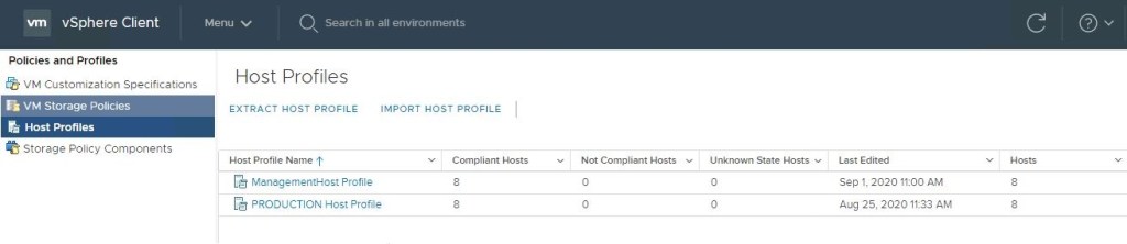
Blog date: September 01, 2020 Completed on vSphere version: 6.7
Today my customer needed to change the root password for roughly 36 hosts across two data centers. These are two data centers that were recently built as part of my residency with them, and they have already seen the benefits of using host profiles. Today I was able to show them one more.
VMware has a KB68079 that details the process should the root password become unknown on a host. Well the same process can be applied and used to update the password on all hosts with that host profile attached. At the time of writing this article, all hosts are compliant with the current host profile, and there are no outstanding issues.
In the vSphere client, go to ‘Policies and Profiles’ and select ‘Host Profiles’ in the left column, click and select the desired host profile on the right.
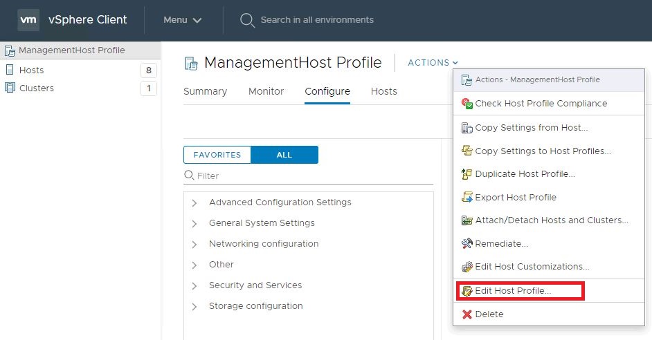
Edit the desired host profile.
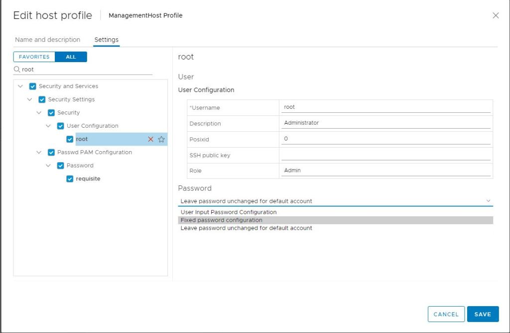
In the search field, type root and hit enter.
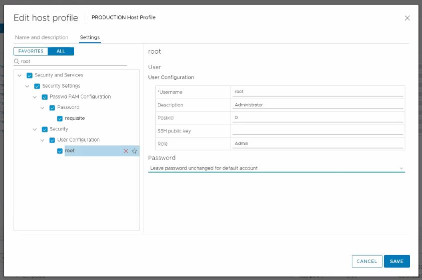
Select root in the left column.
In the right column, change the field below ‘Password’ to Fixed password Configuration.
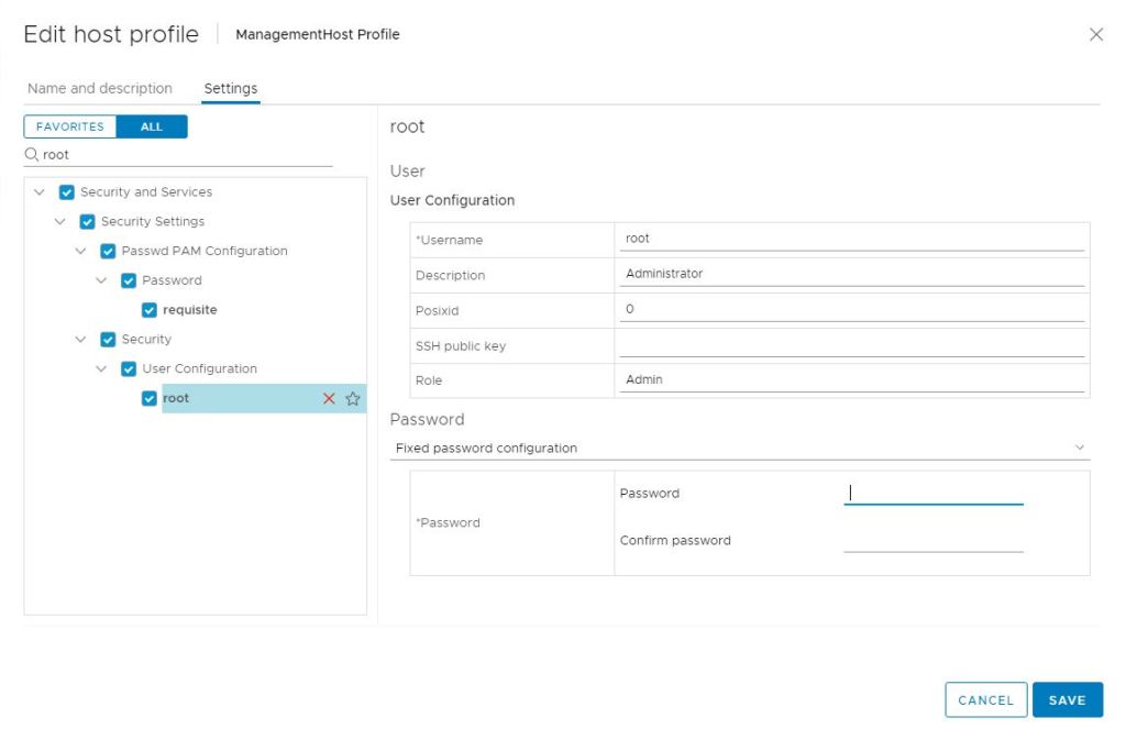
Now you are prompted with password fields and can update the root password.
Click Save once the new password has been entered.
Now you can remediate the hosts against the updated host profile, and the root account will get updated on each host. – Out of an abundance of caution, it is always good to spot check a handful of hosts to validate the new password.
I had my customer go back and edit the host profile once more and change the ‘Password’ field back to: Leave password unchanged for the default account. Click save, and then remediate the cluster again. The new password will stay.
Before I connected with the customer today, they had already researched how to update the root password on all hosts with a script, but this method is simple, automated and built into vSphere.
For the purposes of this demonstration, I will be configuring NFS services on a CentOS 7 VM, deployed to a vSphere 6.7 U3 homelab environment.
NFS Server VM Configuration
Host Name: cb01-nfs01 IP Address: 10.0.0.35 CPU: 2 RAM: 4GB
Disk 1: 20GB – Linux installation (thin provisioned) Disk 2: 100GB – Will be used for the vCD NFS share (thin provisioned)
Configure the vCD NFS share disk
For this demonstration, I have chosen not to configure Disk 2 that was added to the VM. Therefore, this “how-to” assumes that a new disk has been added to the VM, and the NFS server has been powered on after.
1) Open a secure shell to the NFS server. I have switched to the root account. 2) On my NFS server, the new disk will be “/dev/sdb”, if you are unsure run the following command to identify the new disk on yours:
fdisk -l
3) We need to format the newly added disk. In my case /dev/sdb. So run the following command:
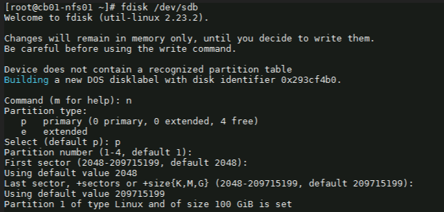
fdisk /dev/sdb
4) Next with the fdisk utility, we need to partition the drive. I used the following sequence: (for new partition) : n (for primary partition) : p (default 1) : enter (default first sector) : enter (default last sector) : enter
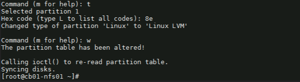
5) Before saving the partition, we need to change it to ‘Linux LVM’ from its current format ‘Linux’. We’ll first use the option ‘t’ to change the partition type, then use the hex code ‘8e’ to change it to Linux LVM like so:
Command (m for help): t Selected partition 1
Hex code (type L to list all codes): 8e Changed type of partition ‘Linux’ to ‘Linux LVM’.
Command (m for help): w
Once you see “Command (m for help):” type ‘w’ to save the config.
Create a ‘Physical Volume, Volume Group and Logical Volume
6) Now that the partition is prepared on the new disk, we can go ahead and create the physical volume with the following command:
# pvcreate /dev/sdb1
7) Now we to create a volume group. You can name it whatever suites your naming standards. For this demonstration, I’ve created a volume group named vg_nfsshare_vcloud_director using /dev/sdb1, using the following command:
# vgcreate vg_nfsshare_vcloud_director /dev/sdb1
Creating a volume group allows us the possibility of adding other devices to expand storage capacity when needed.
8) When it comes to creating logical volumes (LV), the distribution of space must take into consideration both current and future needs. It is considered good practice to name each logical volume according to its intended use. – In this example I’ll create one LV named vol_nfsshare_vcloud_director using all the space. – The -n option is used to indicate a name for the LV, whereas -l (lowercase L) is used to indicate a percentage of the remaining space in the container VG. The full command used looks like: # lvcreate -n vol_nfsshare_vcloud_director -l 100%FREE vg_nfsshare_vcloud_director
9) Before a logical volume can be used, we need to create a filesystem on top of it. I’ve used ext4 since it allows us both to increase and reduce the size of the LV. The command used looks like:
Writing the filesystem will take some time to complete. Once successful you will be returned to the command prompt.
Mounting the Logical Volume on Boot
10) Next, create a mount point for the LV. This will be used later on for the NFS share. The command looks like:
# mkdir -p /nfsshare/vcloud_director
11) To better identify a logical volume we will need to find out what its UUID (a non-changing attribute that uniquely identifies a formatted storage device) is. The command looks like:
To see that it was successfully mounted, use the following command similar to:
# mount | grep nfsshare
Assign Permissions to the NFS Share
14) According to the Preparing the Transfer Server Storage section of the vCloud DIrector 10.0 guide, you must ensure that its permissions and ownership are 750 and root:root .
Setting the permissions on the NFS share would look similar to:
# chmod 750 /nfsshare/vcloud_director
Setting the ownership would look similar to:
# chown root:root /nfsshare/vcloud_director
Install the NFS Server Utilities
15) Install the below package for NFS server using the yum command:
# yum install -y nfs-utils
16) Once the packages are installed, enable and start NFS services:
# systemctl enable nfs-server rpcbind
# systemctl start nfs-server rpcbind
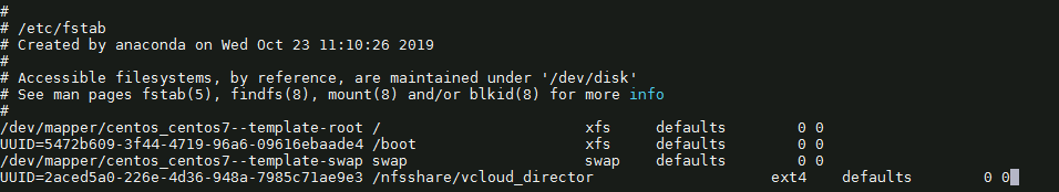
16) Modify /etc/exports file to make an entry for the directory /nfsshare/vcloud_director .
– According to the Preparing the Transfer Server Storage guide, the method for allowing read-write access to the shared location for two cells named vcd-cell1-IP and vcd-cell2-IP is the no_root_squash method.
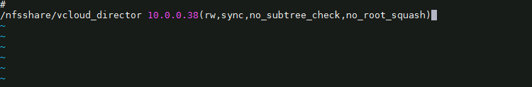
# vi /etc/exports
17) For this demonstration, my vCD appliance IP on the second nic is 10.0.0.38, so I add the following:
– There must be no space between each cell IP address and its immediate following left parenthesis in the export line. If the NFS server reboots while the cells are writing data to the shared location, the use of the sync option in the export configuration prevents data corruption in the shared location. The use of the no_subtree_check option in the export configuration improves reliability when a subdirectory of a file system is exported. – As this is only a lab, I only have a single vCD appliance for testing. If a proper production deployment, add additional lines for each appliance IP.
18) Each server in the vCloud Director server group must be allowed to mount the NFS share by inspecting the export list for the NFS export. You export the mount by running exportfs -a to export all NFS shares. To re-export use exportfs -r.
# exportfs -a
– To check the export, run the following command:
# exportfs -v
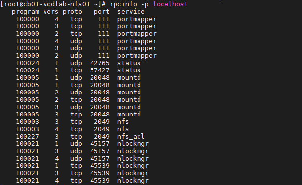
– Validate NFS daemons are running on the server by using rpcinfo -p localhost or service nfs status. NFS daemons must be running on the server.
# rpcinfo -p localhost
or
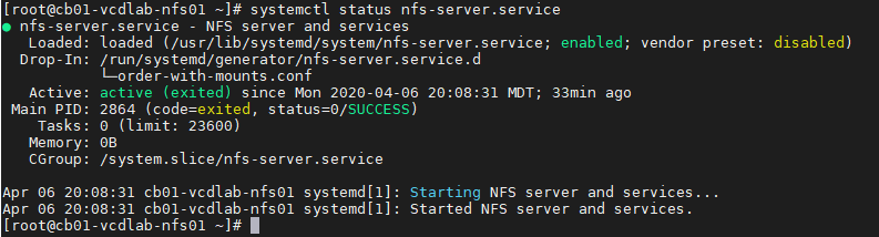
# systemctl status nfs-server.service
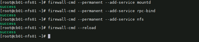
Configure the Firewall
19) We need to configure the firewall on the NFS server to allow NFS client to access the NFS share. To do that, run the following commands on the NFS server. # firewall-cmd --permanent --add-service mountd # firewall-cmd --permanent --add-service rpc-bind # firewall-cmd --permanent --add-service nfs # firewall-cmd --reload
20) That’s it. Now we can deploy the vCloud Director 10.0 appliance(s).
Optional NFS Share Testing
I highly recommend testing the NFS share before continuing with the vCloud DIrector 10.0 appliance deployment. For my testing, I have deployed a temporary CentOS 7 VM, with the same hostname and IP address as my first vCD appliance. I have installed nfs-utils on my test VM. # yum install -y nfs-utils
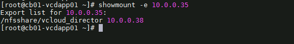
OT-1) Check the NFS shares available on the NFS server by running the following command on the test VM. change the IP and share here to your NFS server.
# showmount -e 10.0.0.35
As you can see, my mount on my NFS server is showing one exported list for 10.0.0.38, my only vCD appliance
OT-2) Create a directory on NFS test VM to mount the NFS share /nfsshare/vcloud_director which we have created on the NFS server. # mkdir -p /mnt/nfsshare/vcloud_director
OT-3) Use below command to mount the NFS share /nfsshare/vcloud_director from NFS server 10.0.0.35 in /mnt/nfsshare/vcloud_director on NFS test VM.
# mount 10.0.0.35:/nfsshare/vcloud_director /mnt/nfsshare/vcloud_director
OT-4) Verify the mounted share on the NFS test VM using mount command.
# mount | grep nfsshare
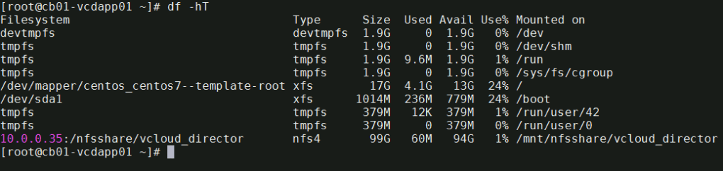
You can also use the df -hT command to check the mounted NFS share.
# df -hT
OT-5) Next we’ll create a file on the mounted directory to verify the read and write access on NFS share. IMPORTANT** during the vCD appliance deployment, it is expected that this directory is empty, else it could make the deployment fail. Remember to cleanup after the test.
# touch /mnt/nfsshare/vcloud_director/test
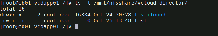
OT-6) Verify the test file exists by using the following command:
# ls -l /mnt/nfsshare/vcloud_director/
OT-7) Clean your room. Cleanup the directory so that it is ready for the vCD deployment.
# rm /mnt/nfsshare/vcloud_director/test
After successfully testing the share, we now know that we can write to that directory from the vCD appliance IP address, and that we can remove files.
In my next post, I will cover deploying the vCloud Director 10.0 appliance. Stay tuned!
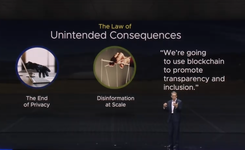
The start of VMworld 2019 in San Francisco is underway, and Pat kicked off the general session talking about his excitement for being back in San Francisco, while poking fun at us “Vegas lovers”. Pat also talked about technology, our digital lives, and technologies role being a force for good. He talked about charities, and cancer research foundations.
Pat Then talked about The Law of Unintended Consequences, and how technology has advanced, we as a society have given up certain aspects of Privacy, the need to combat disinformation at scale available widely on the social media platforms.
Surprisingly, according to Pat, Bitcoin is Bad and contributes to the climate crisis.
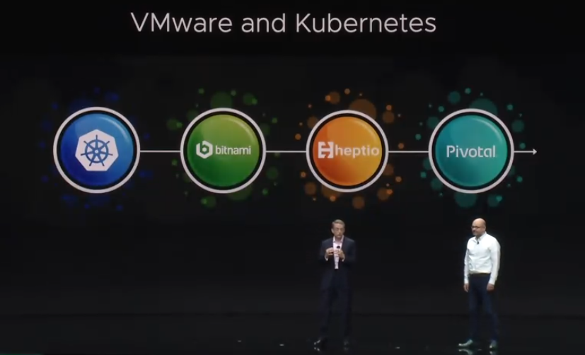
First Major Announcement with Kubernetes, as VMware has been focussing on containers
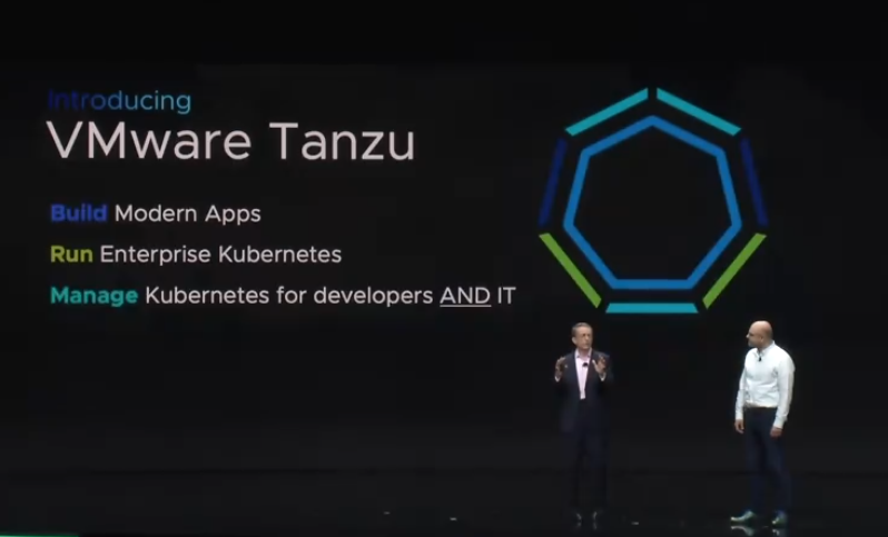
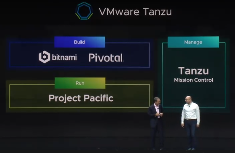
Pat then announced the creation of VMware Tanzu, which is the initiative to have a common platform that allows developers to build modern apps, run enterprise Kubernetes, and platform to manage Kubernetes for developers and IT..
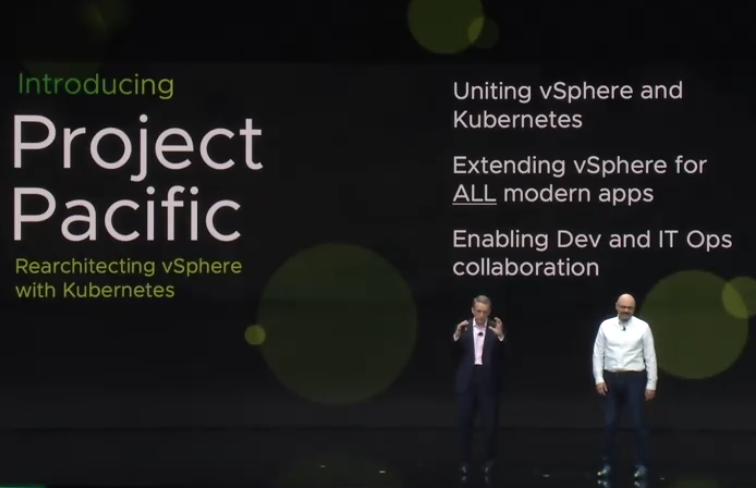
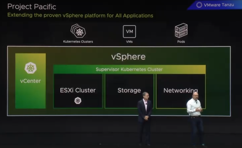
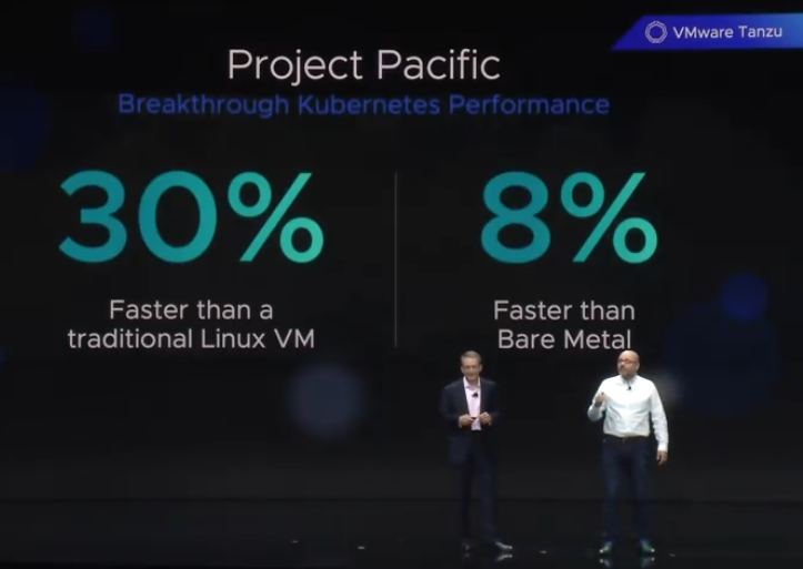
Second Major Announcement, Project Pacific. An ambitious project to unite vSphere and Kubernetes for the future of modern IT
Interestingly, Project Pacific was announced to be 30% faster than a traditional Linux VM, and 8% faster than solutions running on bare metal.
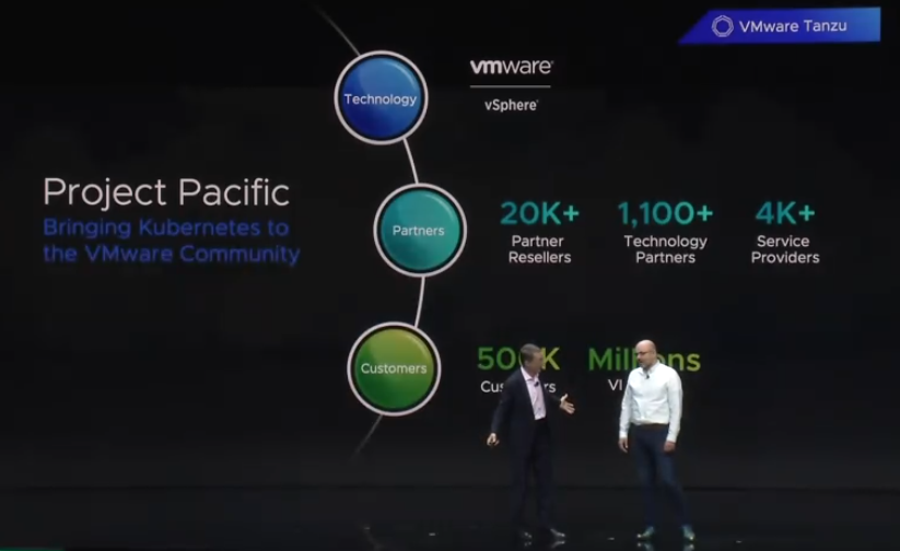
Project Pacific brings Kubernetes to the VMware Community, and will be offered by 20K+ Partner resellers, 4K+ Service providers and 1,100+ technology partners.
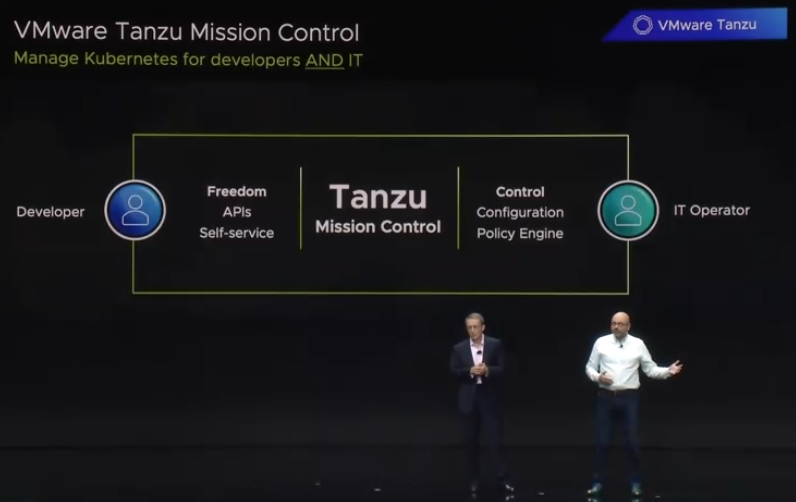
Tanzu also comes with mission control, a centralized tool allowing IT Operations to manage Kubernetes for developers and IT.
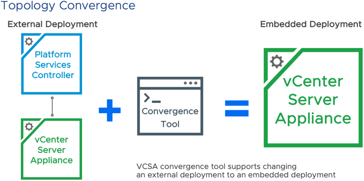
In this second part of the blog series “Upgrading to vSphere 6.7 Update 1, and Using the vCenter Converge Tool”, I will go over my experience using the Convergence tool. Lets get started.
For this customer, I had three vCSA’s and three PSC’s that I needed to converge. Most of the blogs that I found didn’t cover PSC’s that were joined to a domain, environments with multiple vCenters, or with multiple PSC’s, so I thought I would write this up in a blog.
Planning the Convergence
The first thing I had to do was take note of any registered services with the SSO domain. I utilized VMware’s KB2043509 to identify these services, which I had none to worry about. VMware specifically calls out NSX and Site Recovery Manager (SRM), but since those were not in use at this customer, the only things I had to worry about were Horizon, vROps, vRLi and Zerto. Each of these services registered directly to the vCenters, so I had nothing to worry about there. If I had any services registered with the SSO domain, I’d simply need to re-register them once the convergence tool was ran. But since this didn’t apply, I can move forward with configuring the scripts for the convergence tool.
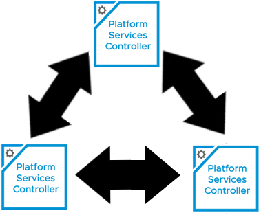
I also need to have an understanding of the replication typology of the existing SSO domain. VMware KB2127057 was an excellent resource I used to gather that information. Opening a putting session to a vCenter, and running the ‘vdcrepadmin’ command against each of the external PSCs, I was able to see the following:
I can see they already have a ring topology, which is the desired architecture. If I were to draw the SSO typology out, it would look something like:
Setting Up the JSON Templates for the Convergence Tool
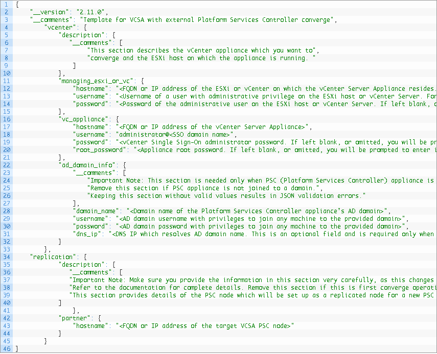
The converge.json template that the convergence tool uses, can be found in the VMware VCSA ISO, that was used for the 6.7 Update 1 upgrade, under the following path: DVD Drive (#):\VMware VCSA\vcsa-converge-cli\templates\
To make my life easier, I copied the contents of the entire ISO to a folder on the root of my C drive. I then made a seperate folder on the root of C called converge, and created a folder for each of the three vCenters I’d be working with: vCenter-A, vCenter-B, vCenter-C. I made a copy of the converge.json, and placed it into each folder.
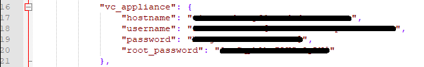
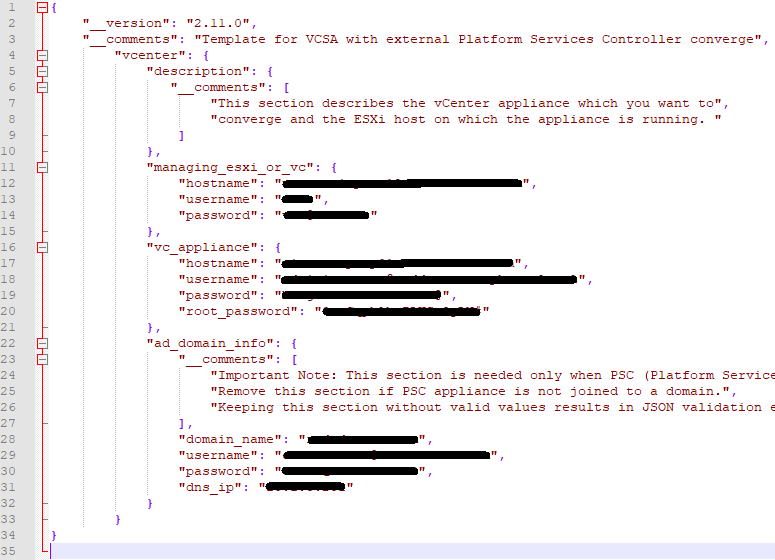
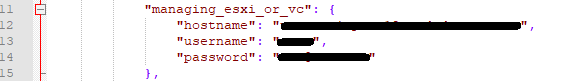
Taking a look at the converge.json for vCenter-A, the template tells you what data needs to be filled in, so pay close attention. Lines 10 – 15 needs entries for the ESXi host where the vCenter resides, or the managing vCenter appliance. Here I chose the option to used the Managing ESXi host. All I needed to do, was look in vSphere to see where the vCSA appliance VM resided on which host. While there, I also set the Cluster DRS settings to manual, to prevent the VMs from moving during the upgrade. Once I obtained the information needed, I completed that portion of the json. (I’ve redacted environment specific information).
Lines 16 – 21 need data entries for the first vCenter appliance (vCenter-A) to be converged. Here I need the FQDN for vCenter-A, for the Username, I need the administrator@vsphere.local account, its password, and the root password of the appliance.
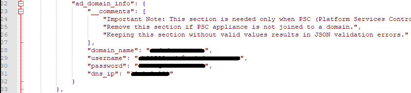
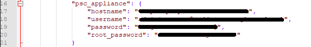
Lines 22 – 33 would be filled out IF the Platform Services Controller (PSC) appliance is joined to the domain. My customer was joined to the domain, so I needed to fill this section out. Otherwise you can remove this section from the JSON.
Now, because this is the first vCenter of three, in the same SSO domain, for the first convergence, I did not need this section, because the first vCenter does not have a partner yet. It will be needed however, on the second (vCenter-B) and third (vCenter-C) convergences.
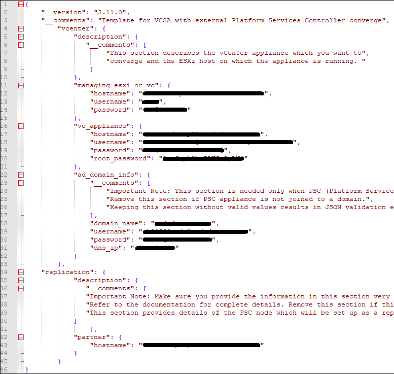
Now I need to fill out a second and third converge.json file for the second and third convergence, saving each in its respective folder. For vCenter-B and vCenter-C, for the partner hostname on line 32, I used the FQDN of the first converged vCenter (vCenter-A), as that is the first partner of the SSO domain.
For vCenter-A, the first to be converged, the completed converge.json looks like this (take note of the commas, brackets and lines removed):
For the second convergence (vCenter-B), and third convergence (vCenter-C), the completed converge.json looks like this:
Now that we got the converge.json done for each of the vCenters, we can work on the decommission.json.
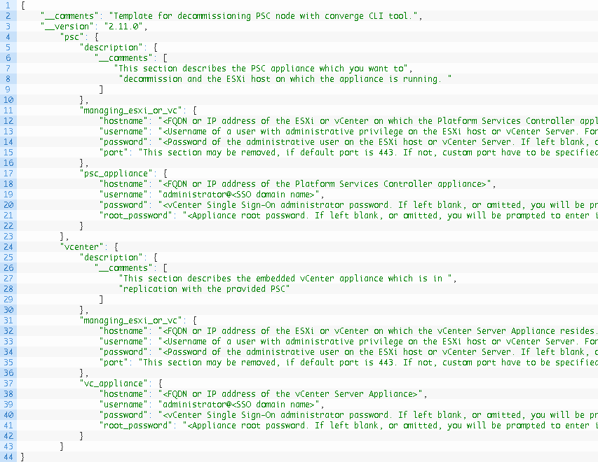
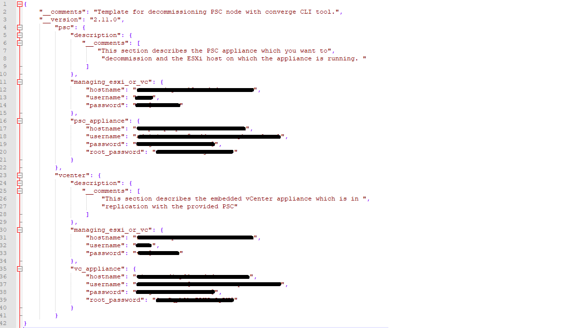
Here is the template VMware provides in the same directory:
Lines 11 – 15 require impute for the Managing vCenter or ESXi Host of the External PSC. Again, just like the vCenter, I used the ESXi host that the PSC is running on.
Lines 16 – 21 needs data for the Platform Services Controller that will be Decommissioned.
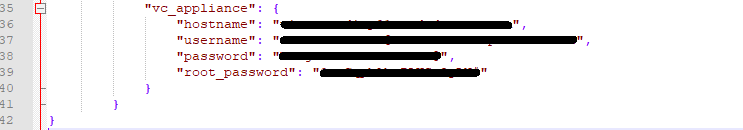
Lines 30 – 34 requires information for the vCenter the PSC was paired with. Again here I just used the ESXi host that the vCenter is currently running on
Lines 35 – 39 require the information for the vCenter, the PSC is paired with.
Now that we have the decommission.json filled out for the first vCenter (vCenter-A), I have to repeat the process for the second and third vCenters (vCenter-B, vCenter-C). The full decommission.json should look like
Now that both the converge.json and decommission.json have been filled out for each of my environments (3), and stored in the same directory on the root of C, I can move forward with the Convergence process.
Prerequisites and Considerations Before Starting the Convergence Process
The converge tool only supports the VCSA and PSC 6.7 Update 1. All nodes must be on 6.7 Update 1 before converting.
If you are currently running a Windows vCenter Server or PSC, you must migrate to the appliance first.
Before converting, take a backups of your VCSA(s) and PSCs in the vSphere SSO domain(VM snapshots, and DB backups).
Know all other solutions using the PSC for authentication in the environment. They will need to be re-registered after the convergence completes and before decommissioning.
A machine on a routable network which can communicate with the VCSA and PSC will be used to run the convergence and decommission process.
Set the DRS Automation Level to manual, and the Migration Threshold to conservative. There will be be issues if the VCSA being converged is moved during the process.
If VCHA is enabled, it must be disabled prior to running the convergence process.
The converge process will handle PSC HA load balancers. Make sure you point to the VIP in the JSON template if you have them.
All vSphere SSO data is migrated with the exception of local OS users.
Best to take snapshots of the vCSA and external PSC VMs before continuing. We’ve already backed up the database, but it doesn’t hurt to have snapshots as well.
Executing the Converge Tool
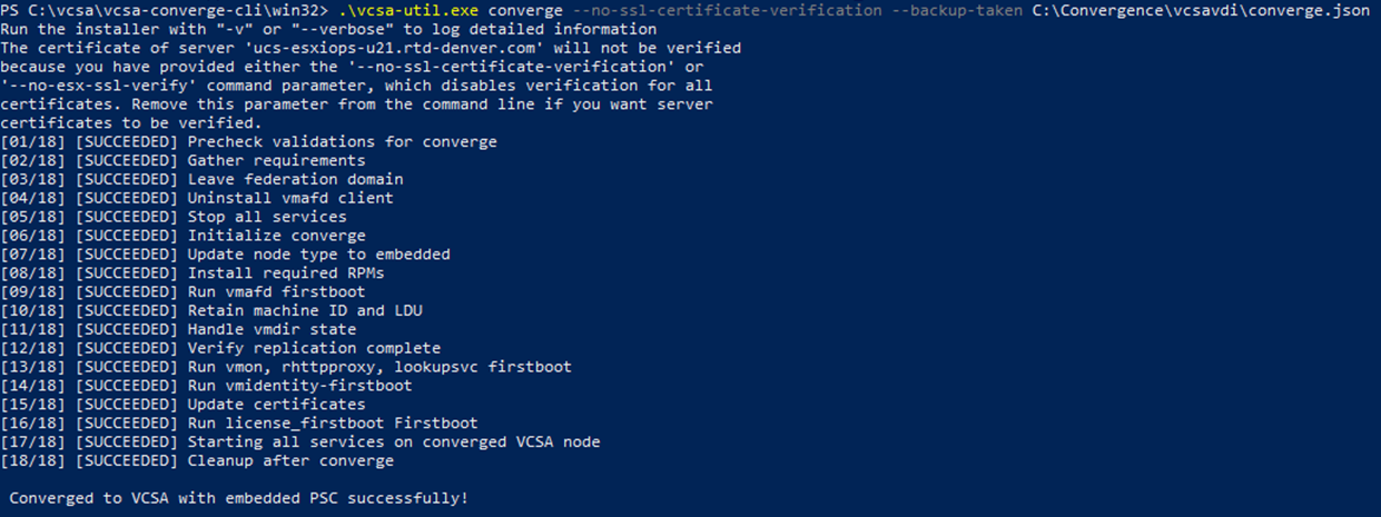
Now that converge.json template for each vCenter (vCenter-A, vCenter-B, vCenter-C) is filled out properly, we can now execute. We will run the convergence tool against the first vCenter (vCenter-A). Note: We can only run the converge tool against one vCSA at a time.
In powershell, we can first run the following command before proceeding with the upgrade to see what options/parameters are available with the converge tool.
The output in powershell should look something like:
It will then ask you to reboot the first vCenter before continuing.
Once the first vCenter (vCenter-A) came up, I executed the convergence tool for the second vCenter (vCenter-B). Once completed I restarted the appliance.
Finally, the last vCenter (vCenter-C) is on deck. I executed the converge.json against that vCenter, and once completed, I restarted it.
Here is where you would need to re-point those systems using the old SSO domain, but since I didn’t have any, I can move forward with the decommissioning steps.
Decommissioning the Old external Platform Services Controllers (PSC)
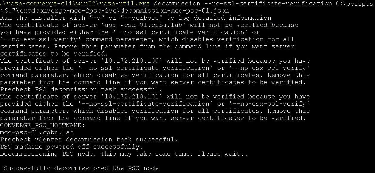
Using the Converge Tool with the decommission option to remove the external PSC’s. Just like before, we need to do this one PSC at a time. The command looks something like this:
Once the process successfully completes, move onto the next PSC. Repeat the process until all PSC’s have been decommissioned.
Validate the SSO Replication Topology After the Converge Process
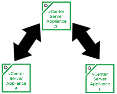
If you’ll remember, when I setup the converge.json, I had the second vCenter (vCenter-B) and third vCenter (vCenter-C) replication partner set to the first converged vCenter (vCenter-A). My Replication topology currently looks like this:
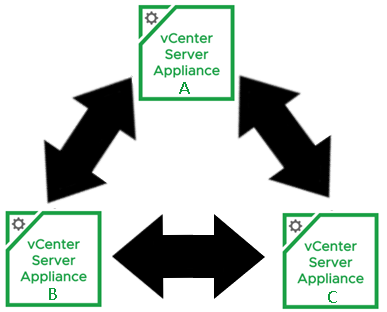
I needed to close the loop between vCenter-B and vCenter-C. Using VMware’s KB2127057 , I used the ‘createagreement’ parameter. I opened a putty session to vCenter-B and ran the following command:
Now that the SSO replication agreement has been made between vCenter-B and vCenter-C, my replication topology looks like this:
I’m not going to lie, the hardest part of using the convergence tool, was just getting started. I’ve been through enough fires in my day to know how bad of a time I would have had if something went wrong, and I lost either the vCenter, or external PSC before the convergence successfully completed. Once I got myself beyond that mental hurdle, the process was actually quite easy and smooth.
I know I’ve left this customer’s environment in a lot better shape than I found it, and having embedded PSCs will make future vCenter upgrades a breeze. For a VMware PSO consultant, this was a huge value add for the customer.


You must be logged in to post a comment.